


Surface-mount technology changed the way we make electronic devices, but it is difficult to understand. Have you ever thought about how gadgets are able to pack on so much yet keep so small? You’re not alone.
It is normal to find the concept of surface mount technology confusing, but don’t worry at all as this article is here to help you. We are going to break down SMT into very simple steps so that it will be a breeze for you to understand. From amateurs to pros, you get valuable insights that will make your learning curve in assembly easier.
So, let’s get started.
Understanding Surface Mount Technology (SMT)
SMT is a way of mounting electronic components directly onto the surface of a printed circuit board. Unlike traditional THT technology, there are no drilled holes in SMT, thus providing greater speed and efficiency during the assembly process.
Components
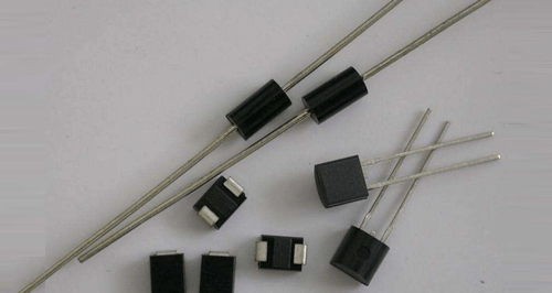
Well, SMD devices are surface mount devices at the center of SMT. These components are smaller and have either no lead or very short leads designed specifically to be mounted on the surface. Commonly Found SMD packages include Ball Grid Array and Quad Flat Package.
Benefits
- Miniaturization:It is possible with SMT to have smaller and lighter electronic devices, a very vital advantage in this information age.
- Higher Density: It allows the number of components to be placed to be increased within a small area of the printed circuit board.
- Better Performance:Shorter paths of the signal translate to improved electrical characteristics and, therefore, better overall device performance.
- Faster Production and Speed:Automation potential inherent in SMT speeds up the production process and reduces manual labor.
The SMT Assembly Process
Here’s the SMT assembly process that you must know:
1)Stencil Printing
The process begins with stencil printing of solder paste onto the PCB. This will eventually make up all the solder joints connecting the components to the board.
The stencil ensures that the paste is applied precisely to the PCB pads where the mounting of the components will take place.
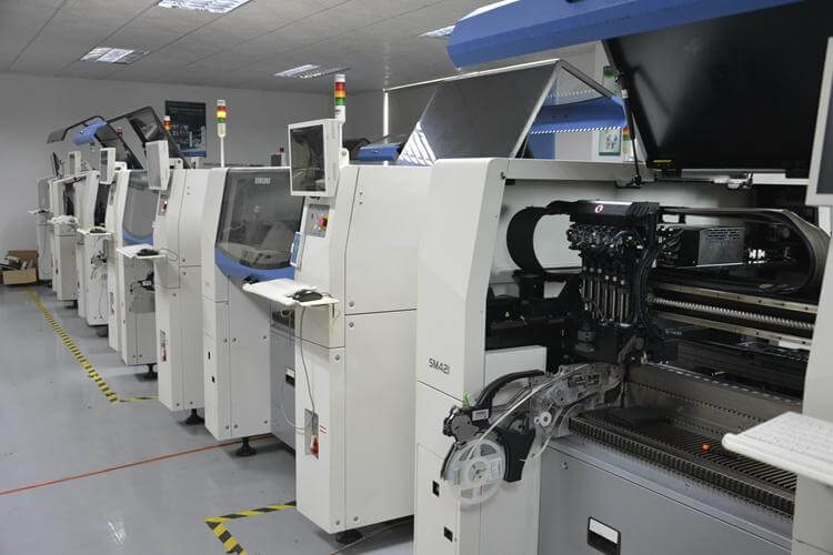
2)Component Placement
Next, solder pastes have the components placed on them using pick-and-place machines. Such automatic machines ensure a level of accuracy that is not only high but also includes speed in the placing of even small components.
This stage of the process helps in maintaining the integrity and performance of the final product since accurate placement will highly influence the reliability of the solder joints.
3)Reflow Soldering
The assembly undergoes the process of reflow soldering. The working principle involves the flow of heat through the reflow oven, making the solder paste meltdown and eventually forming solid electrical connections between the SMDs and the pads on the PCB.
The reflow oven controls the temperature in order to ensure that the solder paste melts and solidifies correctly without damaging components or the PCB.
4)Inspection and Cleaning
Finally, visual verification with cleaning is conducted on the assembled board. AOI systems verify any defects, checking for each connection to be secure and in place.
The remaining residue from the solder paste is cleaned off, ultimately leaving behind a clean and functioning PCB ready for further testing or integration into a bigger system.
Types of SMT Components
As said above, there are different kinds of SMT components. Let’s discuss them in detail:
1.Ball Grid Array (BGA)
The Ball Grid Array (BGA) is a package type for Surface Mounted Devices (SMD) of integrated circuits. On the underside, there are correspondingly attached lots of solder balls to the package, making contact with the PCB pads.
This design allows very high density within a very small footprint and provides BGAs with great suitability for complex circuits such as processors and memory chips. Primary advantages of BGAs include excellent heat dissipation and electrical performance, but the hidden solder joints make them a little tricky to inspect and repair.
2.Quad Flat Package (QFP)
The next popular SMD type is a quad flat package (QFP). QFPs have leads that extend from all four sides of the package. With this device, the leads are soldered to the pads on a PCB. Then, it provides a large number of connections; in comparison, for example, with BGAs, it allows easy inspection and repair.
High performance and reliability, especially in microcontrollers and digital signal processors, are ensured owing to the presence of QFPs.
3.Other Common SMD Packages
- Small Outline Integrated Circuit (SOIC): SOICs are smaller than QFPs and have leads on two sides. They are used for a variety of applications, including memory chips and operational amplifiers.
- Plastic Leaded Chip Carrier (PLCC): PLCCs have leads on all four sides like QFPs, but the leads are bent underneath the package. They offer good protection for the chip and are used in a variety of applications.
- Chip Resistors and Capacitors: These are the most basic SMDs, used for resistive and capacitive functions in circuits. They come in various sizes and values to fit different design requirements.
Each type of SMT component has its own advantages and is chosen based on the specific needs of the electronic device being manufactured. Understanding the different types of SMD packages helps in designing efficient and reliable PCBs.
SMT Process Control
The success of Surface Mount Technology (SMT) heavily depends on precise process control. Key parameters such as solder paste viscosity and reflow temperature profiles must be carefully managed to ensure high-quality and reliable assemblies.
- Solder Paste Viscosity
The viscosity of the solder paste affects how well it adheres to the stencil and PCB pads during the printing process. If the paste is too thick, it can lead to insufficient deposition, while a paste that is too thin can spread excessively and cause bridging between components.
Consistent viscosity ensures that the right amount of solder is deposited, leading to strong and reliable solder joints.
- Reflow Temperature Profiles
The reflow soldering process requires precise temperature control to melt the solder paste and form solid electrical connections.
A well-defined temperature profile ensures that the solder paste reaches the correct melting point without overheating and damaging the components or the PCB.
The profile typically includes a preheat stage, a soak stage, and a peak temperature stage, each carefully monitored to ensure optimal soldering.
Design Considerations for SMT
Here are some design consideration for SMT to help you:
- Pad Design
Pad design in Surface Mount Technology (SMT) is crucial for reliable solder joints and electrical connections. Well-sized pads ensure proper solder paste deposition, preventing solder bridging between adjacent pads. Clear and consistent pad design facilitates efficient assembly and reliable device performance.
- Component Placement
Effective component placement optimizes manufacturing efficiency and operational reliability in SMT. Consistent orientation and symmetrical placement simplify automated assembly, ensuring uniform soldering and optimal signal trace routing.
Adequate clearance between components prevents physical interference and supports thorough inspection.
- Thermal Management
Thermal management techniques, like thermal vias and heatsinks, dissipate heat from sensitive components. Thermal relief pads reduce stress during soldering, enhancing reliability over time.
- Signal Integrity
Careful signal trace routing minimizes signal loss, EMI, and crosstalk in SMT. Short, direct traces and controlled impedance routing preserve signal integrity, crucial for high-speed and differential signals.
- Assembly Process Compatibility
Optimizing PCB design for assembly involves precise stencil design for solder paste deposition and accommodating assembly tolerances for accurate component placement. Designing for assembly compatibility streamlines manufacturing processes and improves product quality.
- Testing and Inspection
Including test points for ICT and functional testing ensures efficient verification of electronic components. Clear visibility of solder joints and component placement aids inspection, enhancing quality control processes.
Applications of SMT
Surface Mount Technology (SMT) is used in various electronic devices, making them smaller, more efficient, and reliable.
1.Smartphones, Tablets, and Laptops
SMT helps make smartphones, tablets, and laptops compact by fitting many components into a small space. It allows powerful processors, memory, and sensors to be integrated without sacrificing performance.
2.Wearable Devices and Consumer Electronics
In devices like smartwatches and fitness trackers, SMT makes them smaller and lighter. It integrates sensors, displays, and connectivity parts, making these devices sleek and easy to use.
3.Computer Components like CPUs and GPUs
SMT is crucial for high-performance computer parts like CPUs and GPUs. It manages dense connections well, ensuring computers run smoothly and reliably.
4.Medical Devices and Industrial Automation Systems
In medical devices and industrial machines, SMT ensures electronics are small yet powerful. It’s used in precise medical equipment and automation systems for accurate control and data processing.
Potential Drawbacks of SMT
While Surface Mount Technology (SMT) offers many benefits, it also has some challenges to consider:
- Complexity and Need for Specialized Equipment
SMT assembly requires specialized equipment such as pick-and-place machines and reflow ovens. Managing these machines and ensuring precise process control can be complex and requires trained operators.
The initial investment in equipment and training can also be significant for smaller manufacturers or hobbyists.
- Rework Difficulty
Repairing or reworking SMT components can be challenging compared to Through-Hole Technology (THT). SMDs are smaller and mounted directly onto the PCB surface, making them harder to access and replace without specialized tools and skills. This can increase repair time and costs, especially in cases of component failure or design changes.
- Limited Component Selection
While SMT supports a wide range of components, the variety can be more limited compared to THT for certain specialized applications. Some components may not be available in SMD packages or may require custom solutions, limiting design flexibility in specific cases.
Conclusion
Surface Mount Technology has transformed electronics by making devices smaller, more efficient, and powerful. It’s used in smartphones, computers, and medical equipment to fit more components into less space.
By understanding how to use SMT well and considering its challenges, we can keep making better and more reliable electronics.