Ever wondered what break routing is in PCB? Most people involved in PCB manufacturing suffer from this: trying to break PCBs in a way that it is within safety measures, so as not to cause damage.
It may be one of the most significant processes going into the manufacturing of PCBs that will allow for a smoother process and protect your boards. This complete guide is an explanation of routing for breaks, a comparison with other methods, benefits, and recommended practices.
By the end of this guide, you will be well-equipped to know how to improve the manufacturing process of the PCB and avoid common problems.
So, let’s get started.
What is Break Routing
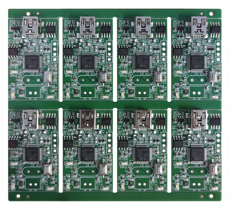
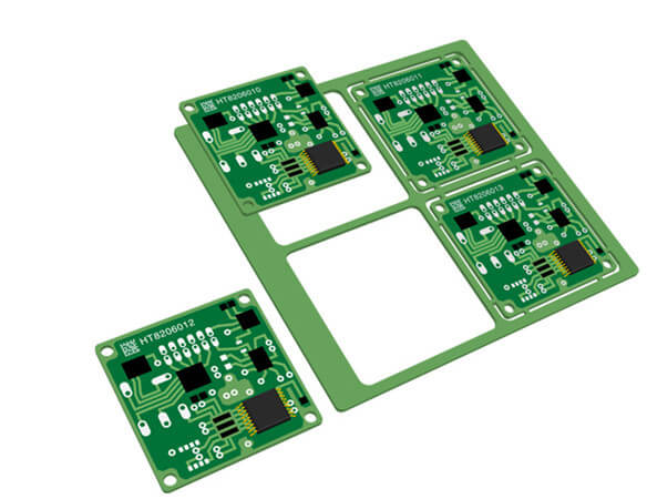
Break routing in PCB is a method used to separate individual printed circuit boards (PCBs) from a larger panel or sheet. This makes use of cutting lines called “break routes” in the PCB material which is needed to break or separate boards. Such cuts are made so that the separation of the boards is easy to break.
Route breaking is an important process in PCB manufacturing. It would then be possible to break out individual boards from this large panel without causing any damage. This feature thus fits especially well in complex PCB designs where precision is of the essence.
Comparison to Other Separation Methods
Let’s compare the break routing with other separation methods:
1.V-cut
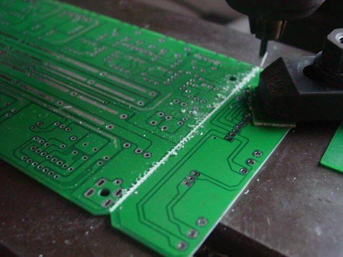
V-cut applies another technique in achieving the separation of PCBs—that is, making a V-groove along the board where the separation does occur.
A V-cut creates a weak point along the groove line, which allows the boards to be pulled apart relatively easily to separate pieces.
However, it sometimes causes problems such as the uneven breaking of the boards and the damaged edges of PCBs, mostly if the lines are not well aligned in the grooves.
On the contrary, break routing helps to create definite separation points with accurate cut lines. This allows for very strongly controlled separation processing with the minimal risk of damaging the boards.
Unlike V-cut which has a groove to help in the separation process, a break routing creates some form of break route where breakage ensues, availing a neater and controlled detachment.
2.Scoring
A mechanical scribe is used in scoring procedures, creating a shallow cut or score line across the board that has multiple PCBs, which it breaks them apart. The scoreline is a weak point, which guarantees proper breaking throughout the panel.
Even though this proves well-thought-out, several instances result in the failure of a crack in one extreme and non-uniform separation of the PCBs in another extreme, particularly in conditions in which the score lines are incorrectly aligned.
Break routing is hence much more controlled way than scoring. In break routing, very fine lines are cut where the places are necessary for separating the boards from each other.
This greatly helps in this separation, to get clean and perfect decomposition. Hence, in this method of creation, no likely harm possibly occurs, and each board is broken off with much better precision.
The Break Routing Process
Break routing involves a series of steps to create precise separation lines on a PCB panel. Here’s a simple breakdown of the process:
1.Designing the Break Routes
The first step consists of designing the break routes, or lines outlined by the PCB to locate the point of separation, given by specific software, and considering the layout of the PCB and the general panel.
2.Tooling and Equipment
This process is carried out by a few special tools, including a CNC router, or a specialized routing machine. Both are programmed to the required shape via a ‘break route’ and cut through the PCB material.
3.Setting Up the Panel
The routing machine is prepared to route the PCB panel. It has to be prepared in a way to support the panel properly, requiring it not to move under the cutting tool.
4.Routing the Break Lines
The routing machine will follow the programmed design, cutting the break routes within the PCB panel, resulting in the separation lines where the boards will break apart. This is to create break-off points between the boards. The machine makes precise cuts, ensuring the routes are consistent and accurate.
5.Break Tab Design and Placement
Break tabs are unclosed sections between the break routes where the board physically bears together until manually separated. In terms of proper design and placement, due importance shall be placed on the tabs making them sufficiently strong enough to hold the boards, yet with ease of opening.
6.Quality Control
Then the panel is routed and checked at the installation. This means examining the alignment of the break routes and boards for any kind of defects or damage.
7.Separation
After the break routes and break tabs are in position the individual PCBs can be manually separated along the break routes. The break tabs are designed to allow this to be carried out easily and smoothly.
Manufacturers will also be better suited to produce high-quality results through these steps while reducing the risk of board damage.
Benefits of Break Routing
Break routing offers several advantages in PCB manufacturing, making it a preferred method for separating boards from a panel.
Here are the key benefits:
- Improved Efficiency in PCB Separation
Deerfoot routing streamlines the separation process, as it creates clear and well-defined cut lines, toward aiding easy, quick separation of single PCBs in comparison with the use of alternative methods.
The cuts create attitudes toward the boards’ separation that are less time-consuming and less laborious.
- Suitability for Complex PCB Shapes
When the loci and trace geometries are very complex, this works best. This offers highly precise separation, much more than other methods of separation, and it helps in those boards that have overly detailed patterns or unusual geometries.
- Reduced Risk of Damage to PCBs
Here, the reduced break routing would then reduce the risk of breakage. The controlled cut ensures that each board is cleanly separated along the lines intended for that, thereby reducing crack chances and cutting down on the PCB edge from damage.
This will result in the production of higher-quality final products with fewer defects.
- Consistency and Precision
CNC routers are used for break routing in conjunction with single-purpose routing machines, such as general break routers or dedicated notchers, as they help maintain the correct, precise cut.
The precision in the cuts is essential so that integrity continues with the PCBs, and each board meets the assumed required specifications.
- Enhanced Handling and Assembly
This also makes handling and assembly easier because break routing allows boards to be cleanly and efficiently separated.
The sharp and clean edges, as well as the well-defined separation lines of the PCBs, make handling and integrating the PCBs into end products easier, creating less chance for errors during assembly.
- Reduced Waste and Cost
Such separation, being efficient with break routing, helps to cut down on material waste and cut production costs.
The high degree of cut accuracy results in reduced scrap and ensures most of the panel material is used in such a way as to contribute to cost savings.
Challenges
Break routing can present several challenges that manufacturers need to address to ensure smooth and effective separation of PCBs:
- Cracking
Cracking along the break routes is a significant challenge. If the PCB material is too brittle or if the routing depth is not controlled properly, cracks can form. These cracks can compromise the integrity of the board and lead to defects or failures.
- Delamination
PCB delamination refers to separating a PCB into different layers by inefficient routing. Deep routing and rough breakaway of the board may lead to this phenomenon. The performance and reliability of the system could suffer because of the delamination of the board.
- Alignment Issues
There will be problems with alignment, in case the routing machine is not calibrated or there is any sort of inaccuracy in the design file. Defects may result from uneven separation and, consequently, the quality of PCBs will be affected.
- Tool Wear and Maintenance
This kind of tearing on routing tools and machines will impair the quality of the routing break process. Maintenance and replacement of worn tools are done regularly to hold the precision in order to avoid problems during routing.
Best Practices for Break Routing
To get the best results with break routing, follow these best practices:
Design Considerations
- Break Route Width and Spacing:Keep break routes between 0.3 to 0.5 mm wide and space them well to avoid overlap and stress. This helps ensure easy separation without damaging the boards.
- Break Tab Design:Design tabs to hold the boards together but make them easy to break apart. Tabs should be strong enough to keep the boards in place but not too strong to make separation difficult.
Tooling and Equipment
- Machine Calibration:Regularly calibrate routing machines for accurate cuts. This prevents alignment issues and ensures consistent break routes.
- Tool Maintenance:Check and replace worn tools to keep them in good condition. Well-maintained tools make cleaner cuts and improve the routing process.
- Routing Techniques
- Controlled Cutting Depth:Set the routing depth carefully to avoid cutting too deep or too shallow. This ensures clean breaks and prevents damage.
- Consistent Speed:Maintain a steady cutting speed for even break routes. Variations can cause inconsistencies and affect separation quality.
Conclusion
Break routing in PCB is a key method for separating printed circuit boards efficiently and without damage. By using precise cut lines, this technique ensures clean separations and is especially useful for complex PCB designs.
While it has benefits, such as improved efficiency and reduced waste, it’s important to address challenges like cracking and alignment issues. Following best practices, such as proper design, regular machine maintenance, and careful routing, can help overcome these challenges.

