


Are you wondering what is a current limiting circuit? If you are concerned about protecting your electronic components from an excessive flow of current, look no further than the current limiting circuit. These circuits play a very important role in keeping devices safe from overloads, short circuits, and malfunctioning.
In this article, we will describe everything you need to know about current limiting circuits. You’ll learn how they work, why they are important, and how you can design your own.
So, let’s begin.
What is a Current Limiting Circuit
The current limiting circuit is an electronic device that aims to limit the maximum current flowing through various circuits. This device, in most cases, limits the current that can be drawn from a Power Supply Unit.
Therefore, it protects the damage of electronic parts from excess current flow due to overloads, short circuits, or malfunctioning of any component.
Current limiting circuits play a crucial role in safeguarding electronic devices.
Here’s why they are important:
- Component Protection:The surge protectors prevent damage to sensitive electronics in your components since they keep the current within safe levels.
- Improved Circuit Reliability:These circuits avoid the overcurrent conditions to their devices, thus significantly improving the net system stability and reliability.
- Safety Enhancement:They reduce the risk of a fire breakout or overheating of the circuit and improve the overall safety of a circuit.
But how do current limiting circuits work? Let’s discuss this in detail.
How Current Limiting Circuits Work
Current-limiting circuits will work just by additionally introducing a component that provides some level of resistance or potential difference into the circuit to control the magnitude of the current flowing through it.
Here’s how this principle works:
- Additional Resistance:By inserting a resistor or another current-limiting device into the circuit, you increase the total resistance. From Ohm’s Law, V = IR; therefore, at constant voltage, this raises the resistance to lower the current. This assures that the current through the circuit being protected is kept below a maximum safe value.
- Voltage Drop: In some cases, the voltage drop introduced by the current-limiting device reduces the effective voltage supplied across the protected circuit. This drop in turn limits the current flowing through the circuit and hence protects sensitive components.
Diagram
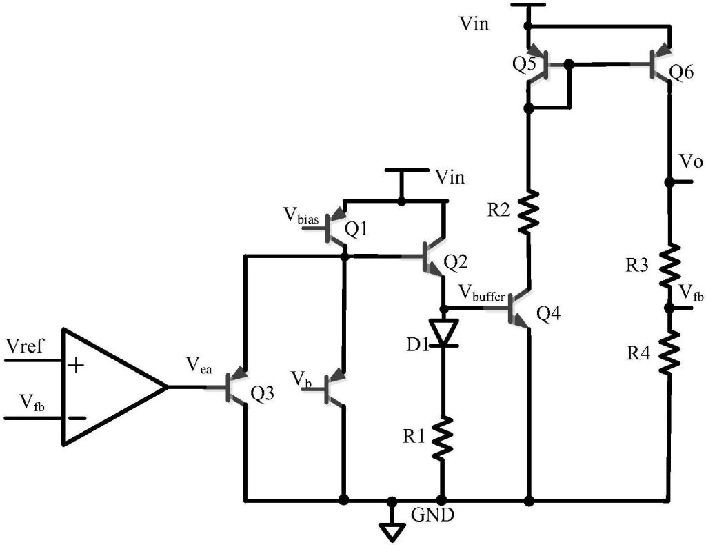
Explanation of Diagram:
- Current Source:Provides the electrical power.
- Current Limiting Circuit:Includes a resistor or other limiting device that restricts current flow.
- Protected Circuit:The part of the circuit that needs protection from excessive current.
In this diagram, there is a power supply through the current limiting circuit before the protected circuit. The current limiter maintains a flow of current through the current limiting component within safe levels so that with an overload or short on the protected side, the amperage cannot rise to destructive levels for the components in the protected circuit.
Benefits of Current Limiting Circuits
Here are some most common benefits of current limiting circuits:
- Component Protection
Current-limiting circuits ensure protection for the delicate electronic parts in your device against currents that could be high enough to be dangerous. Otherwise, such circuits prevent the destruction of sensitive parts due to excessive current.
They help your components proclaim longevity and functionality by keeping the current within a safe range.
- Improved Circuit Reliability
These circuits also enhance the reliability of your electronic systems. They avoid excessive current flowing through the circuit and thus shut off any potential malfunction or failure. Because of this, your devices will no longer break down unexpectedly and function more smoothly.
- Safety Enhancement
Current limiting circuits will maximize safety since there is less overheating and potential fires. A large current may cause the heating up of components that can result in a fire hazard or other dangers.
Hence, such circuits don’t allow the current to go higher than the safe values and keep your devices and users out of danger.
Types of Current Limiting Circuits
There are different types of current limiting circuits. The most common are:
1.Resistor-Based
A simple way to limit current is by using a resistor in series with the protected circuit. The resistor adds resistance, which helps control how much current flows. To get the right amount of current, you need to calculate the resistor value using Ohm’s Law: R = V / I
Here, RRR is the resistance, VVV is the voltage, and III is the current. Picking the right resistor ensures the current stays safe and within limits.
2.Transistor-Based
For more complex needs, transistors can be used to control current. Transistors, like Bipolar Junction Transistors (BJTs) or Field Effect Transistors (FETs), can be set up to adjust the current flow in a more flexible way.
For example, a BJT can be used to keep the current steady by adjusting its operation. When using transistors, make sure to follow safety guidelines and use components that can handle the circuit’s requirements to avoid damage.
3.Integrated Circuits
There are also special integrated circuits (ICs) designed just for current limiting. These ICs are ready-made to handle current control accurately and are used in various applications.
They simplify the design process and ensure reliable performance for keeping current within safe levels.
Now you know the basics of current limiting circuits, let us give you some consideration for designing current limiting circuits.
Considerations for Designing Current Limiting Circuits
Here are some tips for you to help you design current limiting circuits:
- Target Current
The first step in designing a current limiting circuit is deciding the maximum current you want to allow. This is important because it helps you choose the right components and set the limits correctly.
Knowing the target current ensures that your circuit will protect your components from too much current.
- Voltage Drop
When designing your circuit, you also need to consider the voltage drop across the current limiting component, like a resistor or transistor.
This is the amount of voltage lost across the component and affects how well the rest of the circuit works. Make sure the voltage drop is taken into account so that the remaining voltage is enough for your protected circuit to operate properly.
- Power Dissipation
Current limiting components, such as resistors and transistors, turn some electrical energy into heat. It’s important to choose components that can handle this heat without getting damaged.
Check the power ratings of your components and pick ones that can safely handle the heat they will produce to keep your circuit reliable and safe.
How to Calculate Current Limiting Resistor Value?
To calculate the value of a current limiting resistor, follow these simple steps:
- Determine the Desired Current:Decide the maximum current you want to allow through your circuit. For example, if you want to limit the current to 50 mA (0.05 A), note this value.
- Measure the Supply Voltage:Find out the voltage of the power supply that will be used. For instance, if your power supply is 12 V, make a note of this voltage.
- Calculate the Resistor Value:Use Ohm’s Law to find the right resistor value. The formula is R=Vsupply−Vdrop / I, where R is the resistance, Vsupply is the supply voltage, VdropV is the voltage drop across the load (if any), and I is the desired current. For example, if you have a supply voltage of 12 V, a voltage drop across the load of 2 V, and a desired current of 0.05 A, the resistor value would be R= 12-2 / 0.05 = 200 ohms.
- Choose a Resistor with Appropriate Power Rating:Ensure the resistor can handle the power it will dissipate. Calculate the power dissipation using P=I2×R. In this example, P=0.052×200=0.5 watts. Choose a resistor with a power rating higher than this value, like 1 watt, for safety.
Build a Simple Current Limiter Circuit
Here’s a simple guide to build a basic current limiter circuit using a resistor:
Materials and Tools
- Resistor (calculated value)
- Power supply (e.g., 12 V)
- Load (e.g., an LED or small electronic device)
- Multimeter (for measuring current)
- Breadboard and connecting wires
1.Connect the Resistor:
Place the resistor on a breadboard. Connect one end of the resistor to the positive terminal of the power supply.
2.Connect the Load:
Attach the other end of the resistor to one terminal of the load (e.g., an LED or another device).
3.Complete the Circuit:
Connect the other terminal of the load to the negative terminal of the power supply.
4.Check the Current:
Use a multimeter to measure the current flowing through the circuit. Ensure it matches the desired current limit.
5.Adjust if Necessary:
If the current is not within the desired range, adjust the resistor value accordingly and recheck.
This simple circuit helps you ensure that the current through your load stays within safe limits, protecting your components and maintaining proper operation.
Final Words
In conclusion, current limiting circuits are essential for protecting electronic components from excessive current, which can cause damage or failure.
Remember to calculate the correct resistor value and consider factors like voltage drop and power dissipation when designing your circuit.
With these tips, you will be able to build effective current limiting circuits and ensure your electronics work smoothly.