


Without printed circuit board components, no electronic device can exist. Understanding these components can be many times confusing. Do you find it rather difficult to know the various parts of a printed circuit board?
You aren’t the only one; many people struggle to identify these components and know the role they play.
Fear not, for this guide is here to help. We will break down the basics into clear explanations. With all this in one piece, you can see how these simple components work together to power your gadgets.
Thus, let’s get started.
Importance of Components in PCB's Functionality
Much more than this, the components of a PCB are critical on its operation. These represent, so to say, the building blocks which get an electric device going. Each component has a specific job, and together they create a system that manages electrical signals and powers the device.
The connections between components form the heart of every printed circuit board. These connections are responsible for the current through which the device operates.
For example, resistors dictate the current flow, capacitors store and release energy, and transistors amplify signals. When such components are placed and connected correctly, they bring the possibility of a circuit doing almost anything, be it running simple calculations or controlling the operations of more complicated systems like computers and smartphones.
A well-working PCB should have its components chosen and put in place carefully. In so much as one might be broken or missing, the whole circuit might then fail to bring in malfunction to the device. This is why knowledge about the importance and function of each part of the PCB is essential in designing and fixing the equipment.
Now let’s discuss the basic types of PCB components in detail.
Basic Types of PCB Components
PCB components can be divided into two main types: passive components and active components. Each type has specific functions that are crucial for the operation of electronic devices.
1)Passive Components
Passive components control, filter, or store electrical signals without amplifying them, among others.
Here are some of the typical examples:
- Resistors: They resist electrical current flow, just like a hose restricts water. They do it to manage voltage and current that is going to the other components in a circuit.
- Capacitors: The primary function of a capacitor is the storage and release of energy as required. Generally, it is used for filtration to level the fluctuations in voltage and, at the same time, for signal filtering.
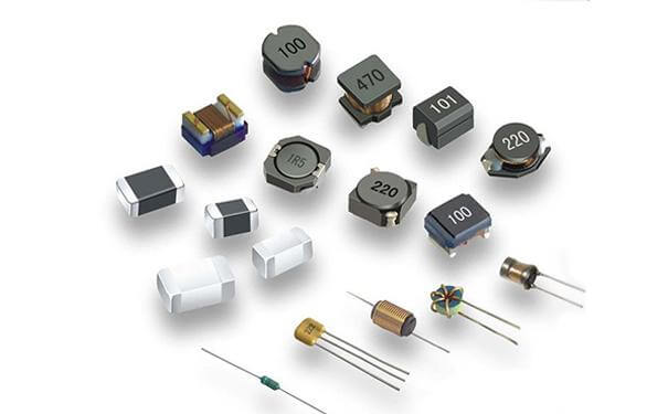
- Inductors: Store energy in a magnetic field when an electrical current flow occurs, usually in filter circuits and tuning systems.
- Diodes:Diodes allow current to flow in one direction only. They are used for rectifying alternating current (AC) to direct current (DC) and in protecting circuits from voltage spikes.
- Light Emitting Diodes (LEDs): LEDs are Light Emitting Diodes that light up when current flows through them. They are used as indicators and in lighting applications.
2)Active Components
Active components can amplify or generate electrical signals. Here are some key examples:
- Transistors: Those devices can serve the purpose of amplifying electric signals or switching, and they represent the basic building blocks in most of the recent electronic gadgets.
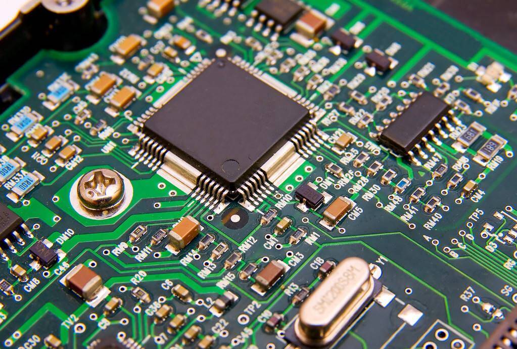
- Integrated Circuits (ICs) are tiny chips capable of many functions ranging from simple logic operations up to rather complicated signal processing, owing to their size. Lots of transistors, among other components, are combined within a small package.
- Operational amplifiers, or op-amps for short, are voltage gain devices used in signal amplification. Mostly, they have myriad applications in sections such as signal conditioning and filtering, plus other purposes in analog sections.
Therefore, these basic types of components on a PCB and their functions should be taken into consideration for designing or troubleshooting an electronic circuit.
All components, in their individual ways, play a specific role so that together they bring efficiency of operation and maximum functionality of the device.
Understanding Component Symbols and Markings
Component symbols are important to electronics because they are used to represent different types of components in a standardized way in a circuit schematic.
These component symbols enable the reading and understanding of complicated diagrams for the proper conveyance of ideas from an engineer to a technician.
Some of the commonly used component symbols are as follows:
- Resistor: Represented by a zigzag line or a rectangle.
- Capacitors: Represented by two parallel lines (non-polarised) or by one straight line and one curved line (polarised).
- Transistors: Represented as a combination of lines and arrows. There are different symbols used to draw out NPN and PNP transistors.
- Integrated Circuits: A rectangle with protruding pins on the sides.
Such symbols enable anybody working on the circuit to pick out any component immediately and be able to comprehend the component’s functioning within the system.
Component Markings
In practical applications, parts are color-coded or labeled with regard to their value, tolerance, and other specifications. Markings on components are very important and allow for the identification of a component, and subsequently the correct use of that component within a circuit.
- Resistors:Typically have color bands showing resistance and tolerance values.
- Capacitors:Typically written with numerals showing the capacitance and voltage value pertaining to that of the rating.
- Transistors and ICs: electronics devices typically carry part number details or other information, coded or printed on the body to facilitate identification of type and specifications.
It is very important for everybody who works with PCBs to have a good understanding of these symbols and markings. It assures that the indicated or desired component is selected and used in the correct manner in order to have proper and functional electronic devices.
Now that you have an overview of the key aspects of PCB components, let’s go into further detail regarding some of the more common packages and how they are mounted.
Common PCB Component Packages and Mounting Styles
There are two primary mounting styles of PCB parts:
1)Through-Hole Technology (THT)
THT components have leads that are inserted into the holes in the PCB and are soldered on the other side of the board. This could easily be recognized by its features, as it has long leads that pass through the board.
Advantages:
- This will provide a strong mechanical bond, and the components will be massive in terms of withstanding physical stress.
- It is easier on the beginner because of the size of the components and holes, making it easier to work with.
Disadvantages:
- Occupies more real estate on the PCB, which reduces the density of components that can be mounted.
More time-consuming to assemble, which can increase manufacturing costs.
2)Surface-Mount Technology (SMT)
SMT is a process where components have small electrodes that get soldered directly onto the surface of the PCB. No leads exist in these components to penetrate through the board.
Advantages:
- Allows more components on the PCB, which is very useful for compact and complex designs.
- Allows fast and cheap assembly, especially for automated manufacturing processes.
Disadvantages:
- It is challenging to work with manually due to the small dimension of the parts.
- Can be less robust under mechanical stress compared to components in THT.
Common SMT Component Package Types
- SOIC: Small Outline Integrated Circuit. A surface-mount IC with gull-wing leads extending from the sides. It finds extensive use for ICs and provides for the laying of components in a compact way.
- DIP (Dual In-line Package):These are mostly related to THT, although there are even some DIP packages in SMT. The two rows are pin-arranged in parallel to each other. DIPs are easy to handle and work with; therefore, they are very suitable for prototyping.
- QFN (Quad Flat No-lead): A high-performance chip package with no lead; there are, instead, pads underneath it for soldering. This is applied when thermal and electrical performance of a high degree is necessary.
- BGA (Ball Grid Array):A package where an array of solder balls is placed on the bottom contacts of the IC. It’s useful for ICs with densely packed pins, like a microprocessor.
It is important to understand these mounting styles and component packages well so that the appropriate parts will be selected for PCB design.
Depending on what exactly you are looking for in your project, each will have specific applications and benefits.
Selecting Components for Your PCB Design
It is essential to choose the correct components according to the application performance and reliability while designing a PCB. Here, consider some parameters:
Functionality
The choice of the right component type is central to attaining a specific electrical behavior in your circuit. Determine what function each component is expected to perform. For example:
- Resistors control the flow of current.
- Capacitors store and release energy.
- Transistors amplify or switch signals.
Ratings and Specifications
Make sure that each component is rated to handle the voltage, current, and power that your circuit will require. Pay particular attention to specifications for:
- Voltage Rating: Maximum voltage which the component can safely handle.
- Present Rating: Max current the component can support.
- Power Handling: Maximum input power allowable for the respective component.
Cost Availability and Cost
Look at part availability and the cost. Some specialized components might have very long lead times or be excessively expensive, causing adverse effects that ripple across your project timeline and budget. Look specifically for components better balanced in availability and cost.
Size and Footprint
Choose parts that will fit within the space available of your PCB layout. Small components are space efficient, but might be more difficult to handle and solder. Verify that the footprint of each component is compatible with your PCB.
Manufacturability
Select components compatible with the fabrication process of your choice. This usually comes down to THT vs. SMT:
- THT components: Much easier to solder by hand or for any prototypes where components require proper mechanical strength.
- SMT: Much better for automated assembly and high-density designs; supports modern, small devices.
Taken together, these factors will actually narrow your choices to the best possible components for your PCB design with respect to optimal performance, reliability, and manufacturability.
Final Words
Understanding PCB components is essential for anyone working with electronic devices. From resistors and capacitors to transistors and ICs, each component plays a vital role in making circuits function correctly.
By reading this guide, you will be well-prepared to design and troubleshoot effective, reliable electronic circuits.