


Ever struggled with plugging devices into USB ports, and some just won’t fit or work the way they are supposed to? The answer could very well be in understanding how the USB pinout works.
When you connect a USB cable, each of the pins in that connector plays an essentially important role—whether it may be delivering power, transferring data, or identifying devices. Getting the connections right secures seamless operation between your computer or smartphone and other gadgets.
In this article, we’ll try to help you unmask some of the mysteries of the USB pinouts, such as what lies behind VBUS, D+, D-, ID, GND, etc. By the end, you will confidently navigate the world of USB connectors to ensure your devices communicate without a glitch.
So, let’s get started.
What is USB Pinout
A USB port is a standard interface on PCs, cell phones, and other electronic devices. This connects peripherals like keyboards, mice, printers, and external storage drives. USB ports offer both power supply and data transfer between the PC and its accessories; thus, they are instead very crucial for everyday computing tasks.
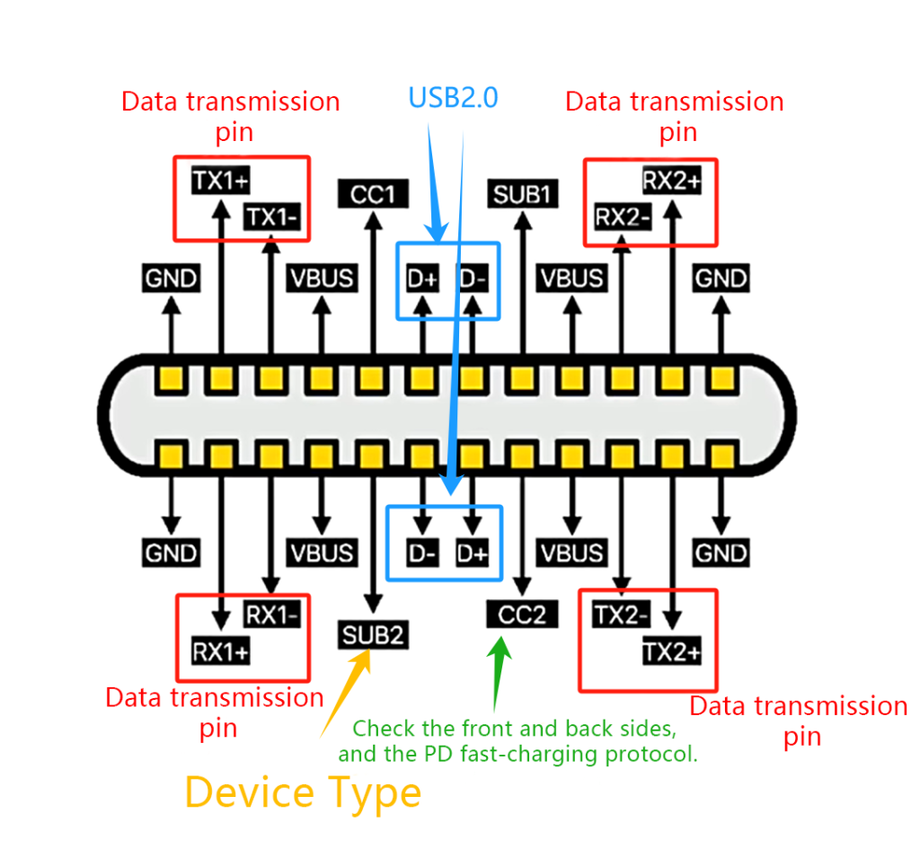
You can envisage a USB pinout similar to a map for how information and power flow through your devices. It’s a diagram of which pins in the USB connector do what.
For instance, VBUS supplies the power, while D+ and Docker- deal with the data transfer. The ID pin differentiates between the host device and peripheral devices, while GND is commonly locates as the ground.
These pins must correspond if you connect devices and want them to interoperate correctly.
Understanding USB Pinout Diagrams
USB pinout diagrams use specific symbols and labels to represent each pin within the connector. These vary slightly depending on the USB standard but usually include:
- VBUS (Voltage Bus): Symbolized by a plus sign (+) or a power symbol (⚡), VBUS provides power to connected devices.
- D+ and D-: These differential data lines are represented by symbols indicating data transmission, often labeled as D+ and D-.
- ID (Identification): Usually depicted by a key symbol or an ID label, this pin helps devices identify whether they are acting as a host or a peripheral.
- GND (Ground): Represented by a ground symbol (⏚), GND serves as a reference point for electrical circuits.
Explaining Each Pin's Role
- VBUS: Supplies power to devices connected via USB.
- D+ and D-: Transmit and receive data signals between devices.
- ID: Determines whether the device is a host (like a computer) or a peripheral (like a keyboard or mouse).
- GND: Provides a common ground reference to ensure proper electrical operation.
Knowing these pinouts allows users to troubleshoot connectivity problems, ensuring that devices work precisely how they communicate.
Types of USB Pinout Configurations
There are different types of USB pinout configurations that you must know:
Standard USB Connectors
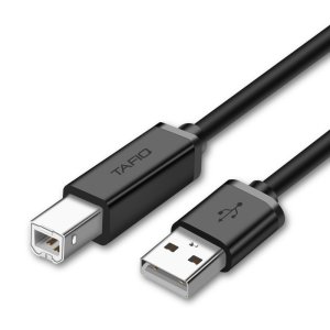
- USB-A: This flat, rectangular connector is commonly found on computers and USB hubs, used for connecting peripherals like keyboards, mice, and external drives.
- USB-B: A square-shaped connector often found on printers, scanners, and some older external hard drives.
Mini-USB and Micro-USB
- Mini-USB: Initially popular in digital cameras and older smartphones, mini-USB connectors are smaller than USB-A and B but larger than micro-USB.
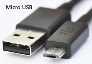
- Micro-USB: Introduced for mobile devices, micro-USB is even smaller than mini-USB and became widely used for smartphones, tablets, and other portable devices.
USB Type-C
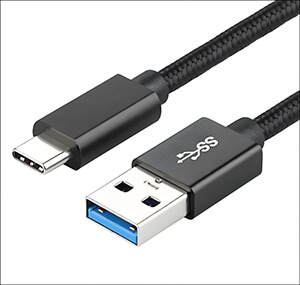
- This modern connector is reversible, meaning it can be plugged in either way, eliminating the frustration of trying to insert it correctly.
- USB-C supports higher data transfer speeds and power delivery capabilities compared to older USB standards.
- It has become the standard for newer devices like laptops, smartphones, and tablets, offering versatility and convenience.
Each USB connector type has its own pinout diagram, detailing the arrangement of pins and their functions. Variations may exist within each type, such as different configurations for power delivery or data transfer speeds.
USB Pinout Functions
Here’s how USB pinout functions:
- VBUS (Power)
VBUS, or Voltage Bus, is responsible for supplying power to the connected device through the USB port.
When you connect a device to a USB port, VBUS provides the necessary electrical power for it to operate. This power can vary depending on the USB standard and the device’s power requirements.
- D+ and D- (Data)
D+ and D- are differential data lines used for transmitting and receiving digital signals between devices.
These lines facilitate data communication between devices, allowing for tasks such as file transfers, peripheral control, and device synchronization. The differential signaling method helps to minimize noise and interference, ensuring reliable data transmission.
- ID (Identification)
ID pin allows devices to identify each other and determine their roles (e.g., USB host or peripheral device).
By detecting whether the ID pin is grounded or connected to VBUS, devices can negotiate their roles in the USB connection. This identification is crucial for proper device communication and functionality.
- GND (Ground)
GND, or Ground, provides a common reference point for the electrical circuit.
It ensures that all connected devices share a common electrical potential, preventing voltage differences that could damage components or disrupt data transmission. GND is essential for maintaining the stability and integrity of the electrical signals within the USB system.
- Additional Pins in USB Standards
Found in USB 3.0 and later standards, SS+ and SS- are differential pairs used for SuperSpeed data transfer.
These pins enable significantly faster data transfer rates compared to earlier USB versions, making them ideal for high-bandwidth applications such as HD video streaming, large file transfers, and fast device charging.
Understanding the functions of each major pin in a USB connector helps users troubleshoot connectivity issues, optimize device performance, and ensure compatibility between different devices and USB standards.
Now you know the basics of USB pinouts, it’s time to discuss it’s applications.
Applications of USB Pinouts
Here are some common applications of USB pinouts:
1.Power Delivery
USB-C’s pinout configuration allows it to deliver higher levels of power compared to older USB standards like USB-A and USB-B. This capability enables faster charging of devices such as smartphones, tablets, and laptops.
USB-C’s ability to handle increased wattage makes it suitable for powering larger devices and peripherals like monitors and external hard drives, simplifying the setup and reducing the number of cables needed for various electronics.
2.Data Transfer
USB pinouts play a crucial role in facilitating smooth data transfer between different devices. Whether you’re transferring files between computers, syncing data between smartphones and PCs, or accessing files on external storage drives, USB pinouts ensure reliable and efficient data transmission.
The differential data lines (D+ and D-) maintain data integrity during transfer, minimizing errors and ensuring that information is transferred accurately and quickly.
3.Device Communication
USB pinouts are essential for enabling communication between devices for both control and data exchange purposes. Peripherals such as keyboards, mice, printers, and external storage drives use USB pinouts to communicate with host devices like computers and smartphones.
The ID pin in USB connectors helps devices identify each other and negotiate their roles (whether they act as a host or a peripheral), ensuring seamless interaction and functionality across a wide range of devices and applications.
Troubleshooting USB Pinout Issues
Here are some additional tips to help you troubleshoot USB pinout issues:
- Incorrect Cable or Connector
Using the wrong cable or connector can lead to compatibility issues between devices. It’s crucial to ensure that the USB pinouts on both ends of the cable match the requirements of the devices you’re connecting.
For example, using a USB-C cable with a device that only supports USB-A may result in connectivity problems or improper functioning.
- Damaged Cable
Physical damage to USB cables, such as cuts, bends, or frayed wires, can disrupt the proper connection between devices. Inspecting cables regularly for any signs of wear and tear and replacing damaged cables promptly can prevent connectivity issues caused by physical damage.
- Driver Issues
Outdated or incompatible device drivers can also cause USB connection problems. Ensure that your device’s drivers are up to date and compatible with the operating system you’re using. Updating drivers can often resolve issues related to device recognition and communication over USB connections.
- Advanced Troubleshooting Methods
For more advanced users or technicians, diagnosing USB pinout issues may involve using tools like multimeters or oscilloscopes. These tools can help measure electrical signals and check for abnormalities in voltage levels or signal integrity along the USB connections.
By analyzing these measurements, users can pinpoint specific issues with USB pinouts and take appropriate actions to resolve them.
Final Thoughts
Understanding USB pinouts is crucial for making devices work well together. Each pin, like VBUS for power and D+ and D- for data, has a specific job that ensures devices connect and communicate smoothly.
By knowing how each pin works and fixing common issues like using the right cable or updating drivers, you can keep your devices running smoothly.