


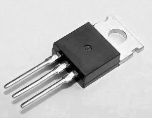
Transistor Pinout and Identification can be tricky, especially if you are new to electronics. Confusing? You might be plagued by the details on how to connect a transistor in your circuit. Well, you are not alone! Knowing how to identify the pins and types of transistors is very essential for any project.
Do not worry because this guide is going to help you. In this article, we are going to help you understand the basics of transistor pinouts and help you identify the various types, and see how they can be connected.
By the end, you’ll feel confident working with transistors. So let’s get started.
What is a Transistor
The transistor is a basic building block of electronics, showing the components acting in a variety of circuits as a switch or an amplifier. It controls electrical current and can turn it on or off or increase its magnitude, depending on what function it performs in the circuit.
Transistors are the unsung heroes of modern electronics—from smartphones to computers. They can be made with many different materials, but most are semiconductors made from silicon.
But what are the transistor types? Let’s discuss this in detail.
Understanding Transistor Types
Basically, there are two kinds of transistors: Bipolar Junction Transistors (BJTs) and Field Effect Transistors (FETs). The former behaves differently than the latter inside electronic circuits; besides, they have a different layout of the pins.
Bipolar Junction Transistors can further be described as current amplifiers. They have two configurations: NPN and PNP. BJTs make use of three pins, the Base, Collector, and Emitter, to control the flow of electrical current.
On the other hand, FETs use an electric field for controlling the current flow. There are many types of Field Effect Transistors, one of which is N-channel MOSFET. It has three pins: Gate, Drain, and Source handling the current flow.
Both BJTs and FETs have specific pinouts, which specify how they can be connected to a circuit, so knowing the layouts is crucial for both circuit design and troubleshooting.
Bipolar Junction Transistor (BJT) Pinout
The two most common configurations of BJTs are NPN and PNP. These configuration types call for current flow in one or the other direction and determine what role each pin plays in any given circuit.
NPN and PNP Configurations
- NPN Transistors: In this configuration, current flows from the collector to the emitter with a small current applied to the base. This quite often used in circuits usually has faster switching times and larger current capabilities.
- PNP Transistors: In this type of transistor, current flows from the emitter into the collector whenever a small current is applied to the base. This configuration again is less common but very useful in particular applications needing this kind of current flow direction.
Pin Diagram and Functions
NPN BJT Diagram
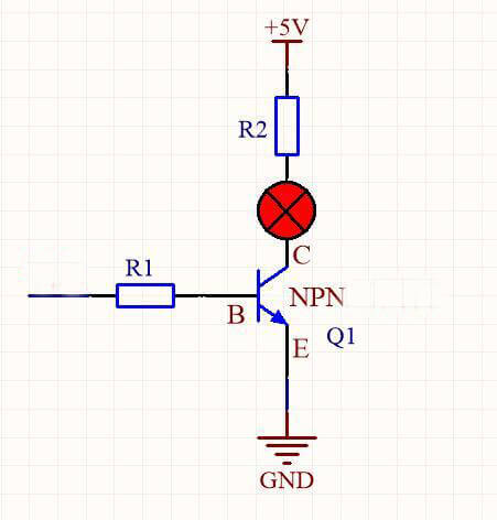
Pin Functions for NPN BJT
- Base (B):This leg controls the flow of current between the collector and the emitter. A small current applied to the base allows a larger current to flow from the collector to the emitter.
- Collector (C): The main current output pin. Current flows from collector to emitter when the transistor is in the ‘on’ state.
- Emitter (E): The current input pin. Current flows out of the emitter in an NPN transistor.
PNP BJT Diagram
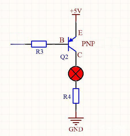
Pin Functions for PNP BJT
- Base (B): It controls the current flow between the emitter and collector. A small current applied to the base allows a larger current to flow from the emitter to the collector.
- Emitter (E): This is the current input pin. In a PNP transistor, current flows into the emitter.
- Collector (C): The primary current output pin. Current flows from the emitter, through to the collector when the transistor is in the ‘on’ state.
The major difference between NPN and PNP transistor operation involves the direction of current flow and also in polarity voltage required to turn on the base.
Field-Effect Transistor (FET) Pinout
Field-Effect Transistors (FETs) are another common type of transistor used in electronics. Unlike BJTs, which use current control, FETs use voltage to control the flow of current.
This makes them ideal for applications requiring high input impedance and low power consumption. FETs come in various types, but one of the most widely used is the N-channel MOSFET (Metal-Oxide-Semiconductor Field-Effect Transistor).
N-channel MOSFET Diagram
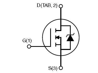
Pin Functions for N-channel MOSFET:
- Gate (G): This pin controls the current flow between the drain and source. Applying a voltage to the gate creates an electric field that allows current to flow through the channel between the drain and source.
- Drain (D): This is the main current output pin. Current flows from the drain to the source when the transistor is ‘on.’
- Source (S): This is the current input pin. Current flows into the source and out through the drain when the gate is activated.
The N-channel MOSFET operates by using a voltage applied to the gate to create an electric field in the semiconductor material, allowing current to flow from the drain to the source.
This type of FET is widely used due to its efficiency and high switching speed, making it ideal for power management and amplification in various electronic devices.
Now you know the basics of transistor type and their pinout. But you must be wondering how to identify the type of transistor based on physical marking or datasheet. Let’s discuss this in detail.
Identifying Transistor Type and Pinout
Identifying the type of transistor (NPN, PNP, or FET) and its pinout is essential for ensuring proper integration into your circuits.
Here’s how you can do it:
Physical Markings
Most transistors have markings on their bodies that indicate their type and model number. These markings can be used to identify whether a transistor is an NPN, PNP, or FET.
Here’s how to decipher them:
- NPN and PNP Transistors: Often marked with the letters “NPN” or “PNP” along with the model number.
- FETs: May have “MOSFET,” “N-channel,” or “P-channel” labels along with the model number.
Using Transistor Datasheets
Transistor datasheets are comprehensive documents provided by manufacturers that contain all the necessary information about a specific transistor, including its type and pin configuration.
Here’s a guide on how to use these datasheets:
- Find the Datasheet: Look up the model number marked on the transistor. You can find datasheets on the manufacturer’s website or specialized datasheet databases like Digi-Key, Mouser, or All About Circuits.
- Check the Type: The datasheet will specify whether the transistor is an NPN, PNP, or FET (N-channel or P-channel).
- Locate the Pinout Section: This section usually includes diagrams and tables showing the pin configuration. It will label each pin (Base, Collector, Emitter for BJTs, or Gate, Drain, Source for FETs).
By using these methods and resources, you can accurately identify and configure transistors in your electronic projects, ensuring proper functionality and performance.
Connecting an LED with a Transistor Pinout
Connecting an LED to a transistor allows you to control the LED with a low-power signal. Here’s how to do it with an NPN BJT and an N-channel MOSFET.
Using an NPN BJT
Components Needed:
- NPN transistor (e.g., 2N2222)
- LED
- Resistor (220 ohms)
- Power supply (5V)
- Breadboard and jumper wires
Steps:
- Place the NPN Transistor: Insert the transistor into the breadboard (Emitter (E), Base (B), Collector (C)).
- Connect the LED:
- Anode of LED to resistor.
- Resistor to power supply (+).
- Cathode of LED to Collector (C).
- Connect the Base Resistor: Resistor between Base (B) and signal source.
- Connect the Emitter: Emitter (E) to ground (-).
- Apply the Signal: Small voltage to the base lights up the LED.
Using an N-channel MOSFET
Components Needed:
- N-channel MOSFET (e.g., IRF540N)
- LED
- Resistor (220 ohms)
- Power supply (5V)
- Breadboard and jumper wires
Steps:
- Place the MOSFET: Insert the MOSFET into the breadboard (Gate (G), Drain (D), Source (S)).
- Connect the LED:
- Anode of LED to resistor.
- Resistor to power supply (+).
- Cathode of LED to Drain (D).
- Connect the Source: Source (S) to ground (-).
- Connect the Gate: Gate (G) to signal source.
- Apply the Signal: Voltage to the gate lights up the LED.
This setup demonstrates practical use of transistor pinouts in controlling an LED.
Conclusion
Understanding transistor pinout and identification is essential for anyone working with electronics. We covered the basics of transistors, including the two main types—BJTs and FETs—and their pin configurations. With this knowledge, you can confidently work with transistors in your projects, ensuring they function correctly in your circuits.