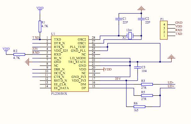
PCB Schematic Definition
PCB schematic is a graphical representation used to illustrate the working principle of a circuit board. It employs graphic symbols to represent circuit components and their connections. Schematic diagrams primarily explain the functional principles of electronic devices without addressing the specific physical layout.

FAQs
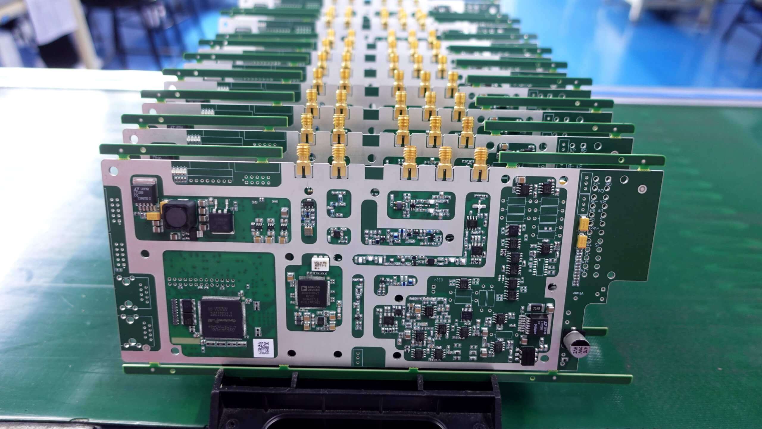
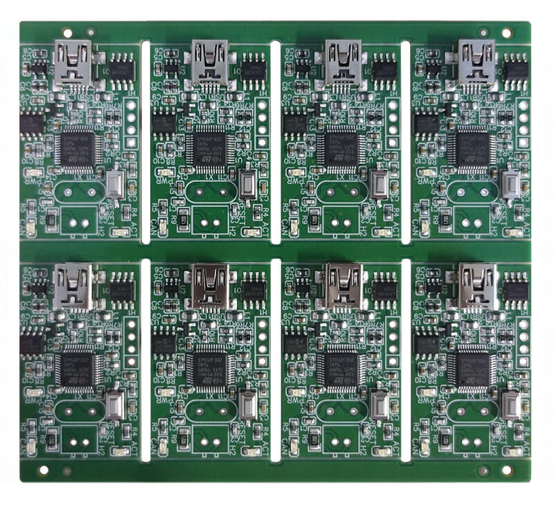
A PCB layout is like a 3D model of a circuit board, which contains accurate information about the component placement, their sizes, pads, signal tracks width, hole diameter, etc. A PCB schematic is a blueprint for the layout. It is essential for reverse engineering the printed circuit board.
*Source:https://www.nextpcb.com
Step 1: Create Or Find A Circuit Diagram.
Step 2: Draw Your Schematics.
Step 3: PCB Design – Your Board Layout.
Step 4: Get Your PCB Made.
Step 5: Order Components.
Step 6: PCB Assembly – Soldering the Components to the Board.
There are three ways to show electrical circuits. They are wiring, schematic, and pictorial diagrams. The two most commonly used are the wiring diagram and the schematic diagram. The uses of these two types of diagrams are compared in Table 1.
*Source:https://sites.ntc.doe.gov
Schematics are usually associated with engineering or electronics. However, any diagram that uses lines and symbols to communicate information can be considered a schematic.
*Source:https://www.lucidchart.com
Zero Defect
Quick-turn service
PCBA Manufacture
Learn how Keep Best can turn your designs into products.


