


Have you ever wondered how your electronic gadgets do their magic? If the thought of a PCB controller sounds overwhelming, do not worry because this article is here to break this myth.
Imagine your device suddenly stops working—it can be very frustrating, right? Well, that is where understanding of the PCB controller comes in handy. These small circuits are the brains of your electronics and control everything down from signals to functions.
In this article, we are going to explain everything about PCB controllers from their types to the designing process and troubleshooting tips that will help you.
So, let’s get started.
What are PCB Controllers
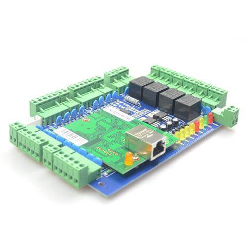
PCB controllers are programmable circuit board controllers, which control electronic devices and manage them to keep their functions running. They are usually microcontrollers or microprocessors that are on the printed circuit board.
They carry out specific functions to the timing, processing of data, and interfacing of other system peripherals as per the program they are tailored to.
What’s significant in PCB controllers is the programmability and the high integration of complex functions in tiny design footprints, which enable applications such as wearables.
They play a crucial role in enabling the functionality of electronic devices by processing inputs, executing logic, and generating outputs according to predefined algorithms and user commands.
Types of PCB Controllers
PCB controllers come in different types, let’s discuss them in detail.
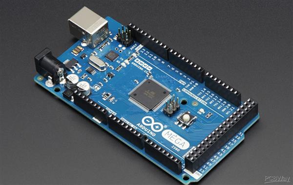
Microcontroller-Based Controllers
Microcontroller-based controllers are widely used in electronics for their affordability and versatility. They integrate a CPU, memory, and peripherals into a single-chip package.
In essence, such controllers only meet the amplitude of applications that need enough processing power but not too hefty for the price paid while keeping power consumption low.
Typical usage includes the systems at home, a car system, and gadgets. Everything has been implemented on AN microcontrollers: from running basic controls to doing complex tasks that receive and process data and interface with the sensory part.
They are small, easy to use, and thus ideal for embedded systems and devices in the IoT environment.
FPGA-Based Controllers (Field-Programmable Gate Array)
FPGA-based controllers are, therefore, very flexible and powerful; they can fit applications that require a real-time data process with complex algorithms and immediate reactions.
FPGAs are inbuilt with programmable logic blocks and connections, so instead of microcontrollers, they provide a sort of openness for a designer to switch up their functions on the designed silicon.
This interestingly flexible feature is apt for tests and implementation changes upon the design in a dynamic fashion within short periods of development.
On top of that, configuring FPGAs involves dealing with some exotic hardware languages like Verilog or VHDL. Because they find utility in tasks such as signal processing and encryption and in industries like aerospace that require more excellent performance and higher customization.
Custom ASICs (Application-Specific Integrated Circuits)
Custom ASICs are the highest-performance, highest-efficiency controllers. These are task-specific chips whereby the need to reduce the speed considers the amount of power used and the integration of complex features down to a single chip.
Off-the-shelf ASICs can’t be reprogrammed after manufacturing, like microcontrollers and FPGAs. Developed ASICs are expensive and take longer to create than off-the-shelf options.
ASICs are applied nowadays in such areas as high-frequency trading, telecommunications, and, to a great extent—medical equipment, where a high level of performance and the reduction in power consumption, area, are essential.
As said above, Microcontrollers are widely used in most common PCB applications, so let’s discuss this in detail.
Understanding Microcontrollers
Let’s discuss key components and microcontrollers’ programming language in detail:
Key Components of Microcontrollers
These are some key points about the microcontroller that you should know:
CPU (Central Processing Unit)
The CPU is the brain of the microcontroller, responsible for executing instructions. It performs arithmetic and logic operations, controls data flow, and manages input/output operations.
Memory
- RAM (Random Access Memory):
Temporary memory utilized to store data and variables during the execution of an application. It is referred to as volatile RAM since it loses the stored contents when the power is turned off.
- ROM (Read-Only Memory):
Stores the firmware or program that initializes the microcontroller when powered on. It is non-volatile, and retains its contents even if power is removed.
I/O Ports (Input/Output Ports)
Interfaces through which the microcontroller communicates with external devices. These ports can be configured as inputs to receive data or outputs to send signals or control devices.
Microcontroller Programming Languages
Microcontrollers are typically programmed using specialized languages tailored to their hardware capabilities.
The most common languages include:
Assembly Language
- Low-level language mapping one-to-one with machine code.
- This allows fine-grained control over the hardware resources it interacts with but remains complex and less portable upon different microcontroller architectures.
C Language
- High-level language that abstracts the hardware’s details in such a way that, for the programmer, it makes writing and maintenance of programs easy.
- It provides portability between different microcontroller platforms and is used widely in embedded system development.
C++ Language
- Object-oriented extension of C; extensions include classes and inheritance.
- Suitable for big, sophisticated projects where it is imperative to structure the code in a way that can be reusable after development.
Such programming languages enable the developer to write codes that control the microcontroller’s behavior, peripheral operation, and data flow very efficiently.
The language is to be chosen based on certain factors that will involve the intricacy of the project, the stipulated performance, and the developer’s know-how in that language.
Designing and Building PCB Controllers
Several systematic steps are carried out in designing and constructing a primary PCB controller.
Let’s discuss them in detail:
1.Define Project Requirements and Functionalities
Clearly define what your PCB controller needs to do. Identify the inputs and outputs it will interface with (sensors and actuators). Understand the control logic of your system and specific needs for operating certain functions.
2.Select a Suitable Microcontroller
Choose your microcontroller according to your project’s complexity, performance requirements, and facilities allowed. Some popular microcontrollers are AVR, PIC, and ARM based on classification.
Some parameters in choosing microcontroller types may include CPU speed, memory size (both RAM and ROM), and the number of I/O pins, along with the availability of development tools.
3.Develop a System Block Diagram
Establish how these connect between the microcontroller, sensors, actuators, and maybe another component. Drawing this diagram will help you visualize how data will be flowing through the system and thereby inform the design.
4.Design the PCB Schematic
Using a PCB design software (e.g., Eagle, KiCad), create a schematic diagram. Place the microcontroller and add supporting components such as resistors, capacitors, and voltage regulators. Design the power circuitry to ensure stable voltage supply to the microcontroller and peripherals.
5.Create the PCB Layout
Convert your schematic design to a PCB layout. Arrange components in ways that are sensitive to reducing noise and interference. Establish good signal integrity through the careful routing of traces, ensuring that there is no crosstalk with another signal.
Also, consider adding ground and power planes for good performance and to support EMI reduction.
6.Write Microcontroller Code using an IDE
Choose an Integrated Development Environment that fits an AVR microcontroller, for instance, MPLAB, PIC, or the Arduino Integrated Developer Environment you are experienced in.
Write code in a programming language such as C or C++ to command the microcontroller’s behavior based on returned characteristics from sensors about physical variables or outputs to actuators based on computation.
7.Fabricate and Assemble the PCB Controller
Once the PCB layout is finalized, send the board for fabrication. Select a good PCB manufacturer available to manufacture your printed circuit boards according to your design specifications.
After receiving the fabricated PCBs, get set with all the required components and start soldering them onto the board, considering your layout.
8.Test and Debug the Controller
Test your PCB controller to ensure it functions correctly according to your project requirements. Use testing equipment to verify sensor readings, actuator responses, and overall system performance. Debug any issues in hardware or software iteratively, making adjustments as needed.
By following these steps systematically, beginners can design and build basic PCB controllers effectively, learning valuable skills in electronics, programming, and PCB design along the way.
Advanced Topics for Experienced Users
- Real-time Operating Systems (RTOS)
Managing most sophisticated tasks in PCB controllers is exercised using a real-time operating system. Unlike general-purpose operating systems, RTOS guarantees accuracies in timing and task prioritization, which are essential in applications where response times are short, and reliability is highly required.
- Power Management Strategies
In electronic devices, at times, efficient operation is called for. Power management techniques are skilled in adequately channeling the energy utilized, thereby extending the life of the battery or reducing the heat dissipated.
Techniques include dynamic voltage scaling, sleep modes, and intelligent power gating.
- Communication Protocols
Communication protocols such as UART, SPI, I2C, and wireless standards like Bluetooth and Wi-Fi facilitate data exchange between PCB controllers and peripherals. Each protocol offers unique advantages in speed, distance, and complexity, catering to diverse application needs.
- Security Considerations
Protecting PCB controllers from cyber threats is paramount. Security considerations involve implementing encryption, authentication mechanisms, and secure boot processes to safeguard data and prevent unauthorized access.
Troubleshooting and Debugging
Here are some tips on troubleshooting common PCB controller issues that will help you:
- Programming Errors
Programming errors can hinder PCB controller functionality. Effective debugging techniques involve using simulators and debuggers to step through code, identify bugs, and simulate inputs to test outputs. This process helps pinpoint errors in logic or syntax, ensuring smooth operation.
- Hardware Malfunction
Troubleshooting on hardware component failure always starts with systematically testing the components. This encompasses checks for damage in physical connectors, the use of multimeters for voltage and continuity checks, and diagnostic tools.
Changing out an identified faulty component or redoing the connections is typically what cures most hardware problems.
- Signal Integrity Issues
The source of signal integrity problems can sometimes be unwanted interferences, noises, or mismatches in impedance caused by electromagnetic intrusion, improper grounding, or insufficient shielding.
Problems generally arise from these phenomena, and the usual remedies are: better signal routing through layout redesign, an increased number of decoupling capacitors, and the use of differential signaling to reduce noise.
Final Thoughts
In conclusion, PCB controllers are crucial for running electronic devices, big and small. This article has given you key insights—from picking microcontrollers to fixing issues like programming errors and signal problems.
With these basics down, you are set to innovate and tackle electronics challenges with confidence. Use PCB controllers to boost device performance and advance your projects in the exciting field of technology.