


Are you wondering how the different parts inside an electronic device are held together to ensure everything works in perfect sync? Well, it is those very links called PCB connectors that make all of this a reality.
Without them, one would find assembling electronics like solving a jigsaw puzzle without some critical pieces.
So in this article, we will discuss the world of PCB connectors. Either for the tech enthusiast, aspiring engineer, or any individual where curiosity gets the better of them about how things work, this essentially means obtaining an understanding of these connectors is critically essential—this ensures that your devices can function without a hitch.
So, let us begin.
What are PCB Connectors
These are the connectors on an electronic device that allow connecting and disconnecting different circuits against a printed circuit board.
They make it easy to assemble, maintain, and repair electronic equipment by providing secure electrical and mechanical connections between various PCBs or between PCBs and other system components, such as sensors, displays, or even power sources.
These connectors come in all sorts of types, shapes, and sizes to suit all requirements, from simple board-to-board connections to advanced multi-pin design configurations.
They stand to ensure the reliability of electrical contact, the integrity of the signal, and mechanical stability within an electronic system.
Types of PCB Connectors
There are different types of PCB connectors used on different boards, which you must know:
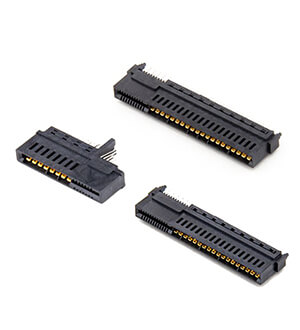
1.Edge Connectors:
The edge connector will provide a consensus physical interface between a printed circuit board and another printed circuit board or backplane, typically used for modules that need removable attachment and to connect different PCBs associated with a subsystem of electronics.
2.Board-to-Board Connectors:
These connectors join two or more PCBs, either stacked or placed next to each other. They may be stackable headers, socket connectors, or specialized interconnects especially designed for specific orientations and configurations.
3.Headers:
This type of connector is usually placed on a PCB to provide connection points for daughterboards, modules, or other components that are plugged in. They are normally used for expansions like the attachment of an LCD display, memory modules, or even communication interfaces like Ethernet ports.
4.Wire-to-Board Connectors:
These provide a link between individual wires and a printed circuit board. They are used to most securely attach external wiring to the PCB, such as one that would occur with a power supply connection or even sensor input.
5.RF Connectors:
These hold good for high-frequency signal transmission. They include types like coaxial connectors, SMA, and BNC, which are imperative in applications where the impedance has been tightly controlled to allow very minimal signal loss typically found in wireless communications systems.
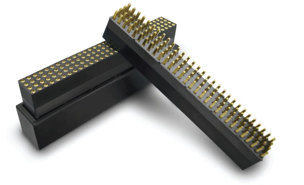
6.Mezzanine Connectors:
Mezzanine connectors are used in specific applications where PCBs should be stacked in a vertical setup having precise and critical conditions of alignment and connection. They allow for compact design while maintaining reliable electrical connections.
Different types of connectors meet needs that span from simple interconnections to specialized high-frequency signal transmission or modular expansions in electronic design.
Now you know the basics of PCB connectors, but you must be wondering what makes these connectors special. Let’s discuss this in detail.
PCB Connector Characteristics
Here are the characteristics of PCB connectors that makes them special:
- Pin Count: The number of electrical connections (pins) a connector provides, which determines how many signals or power lines can be transmitted through the connector.
- Maximum Current Rating: This is the highest current that can be safely passed through a connector without overheating or being damaged. It then becomes essential that this is available so that one has the assurance that it will safely carry the electrical load required for its operation.
- Voltage Rating: This is the highest voltage that can be applied across a connector without the breakdown of insulation or electrical arcing, ensuring safe ops within specified voltage levels.
- Termination Style: How the connector attaches to wires or cables. Common styles include soldering, crimping, or even screw terminals.
- Mounting Style: This refers to how the connector shall be attached physically to the printed circuit board. It could be either through-hole mounted—where pins go through holes in the PCB and get soldered on the other side—or surface mount—where it sits on top of the board’s surface and gets soldered to pads.
- Mating Cycles: This refers to the number of times the plug-and-unplug operations can be reliably done with a connector without degradation in performance. This is critical for connectors used in applications that involve frequent maintenance or need replacement of components or units, as witnessed in test equipment and instrumentation.
These characteristics vary with the type and design of the connector and, hence, must be factored in during the selection of a suitable connector for a given application to ensure compatibility, reliability, and life expectancy in an electronic system.
Applications of PCB Connectors
PCB connectors serve a variety of key applications in electronic systems:
1.Connecting daughterboards to motherboards in computers:
These PCB connectors allow daughter cards to be securely attached to a motherboard so that their functionalities in the form of graphics cards, network adapters, or storage controllers can be easily added to the main circuit board.
2.Enabling inter-board communication in complex electronic devices:
For systems with multiple PCBs, connectors offer a reliable communication link between boards so that data can be interchanged flawlessly and operations synchronized in devices—for example, in industrial control systems or telecommunications equipment.
3.Providing power supply connections to PCBs from external sources:
These connectors supply power, safely and efficiently giving the PCB electrical power from an external source to support smooth device operation—consumer electronics, as well as industrial machinery.
4.Facilitating signal transmission between different parts of a circuit:
Beginning with the PCB connectors, RF and high-speed data connectors, in particular, employ high-frequency signal transmission between circuit components while structuring the signal integrity and potentially minimizing electromagnetic interference for use in telecommunications or high-speed data processing.
5.Allowing for easy connection and disconnection of components for maintenance or upgrades:
Since the specification of connectors with intense mating cycles and secure attachment mechanisms is at the very earliest instance, replacing or upgrading any component within the electronic device will be easy, thus reducing downtime and associated maintenance costs. This assures a reliable performance over the life.
These applications showcase the versatility and importance of PCB connectors in facilitating efficient and flexible designs with the operation of electronic systems across a wide domain of industries and applications.
Selecting the Right PCB Connector
Selecting the right PCB connector for your application involves several key steps to ensure compatibility, reliability, and optimal performance:
1.Identify the required number of connections (pin count):
Determine how many electrical connections—specifically, pins—will be required in your application. This will depend on signals, power lines, and data paths that need to be passed between PCBs or components in any way.
Be sure to have a connector with enough pins for your particular design without over- or under-providing.
2.Determine the current and voltage requirements of your circuit:
Calculate the highest current and voltage your circuit will handle. Choose a connector whose current rating is far higher than what your circuit will ever need so that it can operate safely.
Similarly, select a connector with a voltage rating higher than, or at worst equal to, that of the maximum in your tension circuit to avoid electrical breakdown.
3.Consider the physical space constraints on your PCB:
Measure the available space on your PCB for connector mounting. Consider the size and form factor of the connector to see that it easily fits within the area allotted, without any interference from other components or traces on the PCB.
Determine whether a through-hole or surface mount connector is more appropriate based on your PCB layout and assembly process.
4.Select a connector with compatible termination and mating styles:
Choose a suitable connector that will support an application’s preferred termination method—either soldering, crimping, or screw terminals.
Consider mating styles, such as latch, friction lock, or others, for the connector based upon values like the ease of connection/stainless connection required for assembly, maintenance, or upgrades.
5.For high-frequency applications, choose connectors designed for signal integrity:
If you have an application with a high signal or data transmission frequency, consider how connectors can maintain the integrity of your signal.
Be on the lookout for connectors that offer key features, impedance matching, low insertion loss, and shielding, which will minimize EMI and bring reliable signal transmission.
Following these steps, you can systematically cut down the available options and select a PCB connector that will meet the electrical, mechanical, and environmental demands of your particular application.
Conclusion
In conclusion, PCB connectors are used to connect parts of electronic devices without any hassle. They provide easy assembly, fixing, and upgrading for circuits and other peripheral components.
Whether for a computer, telecommunication apparatus, or machinery, the right choice of a connector would have to mean keeping in mind the pin count, current and voltage handling, size limits, and attachment and disengagement.