


Safety First! Always unplug the device you’re troubleshooting and discharge any capacitors before working on a PCB. Use insulated tools and work in a dry environment to avoid electrical shock.
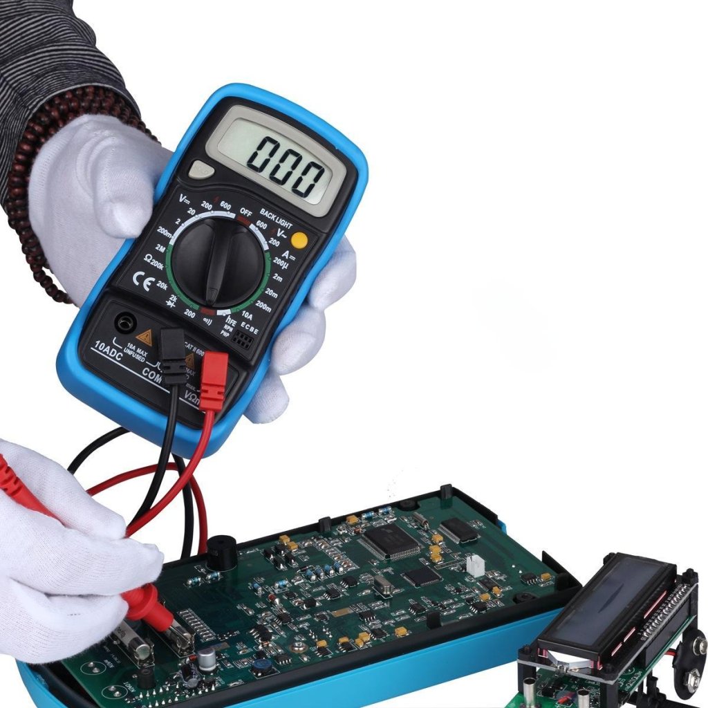
In this guide, we’ll teach you how to test a PCB (printed circuit board) with a multimeter. By understanding how to use a multimeter, you’ll be able to troubleshoot electronics and fix power problems, broken components, and short circuits.
So, let us begin.
Importance of PCB Testing
PCB testing is very crucial to the process of fixing electronics. It helps to find out what is wrong with your devices. For this, a multimeter will be very helpful in testing the voltage, resistance, and continuity. This will give you an idea of where exactly it could be—a broken part or just a lousy connection.
Testing of the PCBs using a multimeter ensures that the electronics work well and are safe to use. This is one of the critical skills for any person involved in repairing or maintaining any kind of electronic device.
Before discussing how to text a PCB with a multimeter, it’s better to first understand multimeter functions.
Understanding Multimeter Functions
For testing PCBs with a multimeter, there are a few key functions you need to be familiar with:
- Voltage Measurement: Use the multimeter in either DC or AC mode, depending on the voltage you intend to measure. Attach these probes with the marked test points on the printed circuit board to let it decide whether power levels are correct.
- Resistance Measurement: This can be used to determine broken parts by showing overflows or short circuits by reading a low value. Using a multimeter in resistance mode (Ω), place the probes across the components or traces and take note of the reading concerning what it should be according to the datasheet.
- Continuity Testing: If there is a path through which electricity can flow, then there is continuity; if not, then there is no continuity. Do this by switching to continuity testing mode and touching probes to each end of the circuit. A beep or some other indicator means the path is complete.
- Other Functions:These meters will also measure current in amps, which are pretty helpful in advanced troubleshooting or when checking how components behave under load.
Mastering these multimeter functions is thus helpful in testing PCBs effectively, isolating the causes of electronic problems precisely.
Preparing for PCB Testing
The following precautious measures should be taken before testing a PCB:
- Safety Precautions: Handling electronics involves risks with electrical shock. Ensure the device is drained and powered off; always use insulated tools and work in a dry environment.
- Setting the multimeter:First, use the selection knob to turn your multimeter to the function to be measured—voltage, resistance, or continuity. Then, adjust the settings and ensure the probes are plugged into the proper ports to get the correct readings.
- Test Point Identification: Test points could be identified from the schematics or markings on the PCB. Schematics indicate where voltage can be meas ured or components tested. Markings on the printed circuit board usually identify those critical spots for troubleshooting.
Performing Basic PCB Tests
Here is the step-by-step procedure for testing a printed circuit board using a multimeter.
1. Voltage Measurement
- Switch the multimeter to DC voltage mode.
- Identify the power rails or other particular component pins you need to measure across the PCB.
- Place the black probe to the ground on a ground point or standard; the red investigation goes to the test point or pin (positive).
- Read the voltage indicated on the multimeter. This reading is then compared with the expected voltage levels from either the service manual or the specifications for that PCB.
2. Testing the resistance of a component
- Set the multimeter to ‘Ω’ to measure resistance.
- Identify the Component to be Tested on the PCB.
- Touch the probes across the component terminals or traces.
- Read the value of resistance displayed on the multimeter and note it against the values specified in the component datasheet.
3. Using Continuity Testing
- Turn your multimeter to Continuity Function, Generally denoted by a diode or sound wave symbol.
- Touch one probe at one end of the trace or to a connection point and another probe at another end.
- Wait for a beep or continuity indication on the multimeter display.
- Continuity means there is a complete path; if not, it could be an open circuit or break.
Using these examples and illustrations of how to do voltage testing, evaluating component resistances, and ensuring circuit continuity in your PCB will help.
Specifically, the tests are crucial to identify and solve any electronic problem accurately.
Troubleshooting Common PCB Faults
Multimeter measurements may well present the basis for diagnostics during regular failures in PCBs and help troubleshoot and rectify faults.
Here’s how they can help identify and fix these issues:
1. Non-functional Circuits due to Power Supply Issues (Low Voltage):
When the circuit does not work, one of the most immediate issues could be insufficient power. This can be checked for with a multimeter in DC voltage mode: Place the black probe on any circuit ground and the red probe on a power supply or input in the circuit. The voltage binds on the meter.
If it’s much lower than expected (from the circuit specs), there’s likely a power issue like a weak battery or a broken power connection. Fixing these problems gets the circuit working again.
2. Open Components Causing Circuit Interruptions (Infinite Resistance):
An open component can shut off the electricity flow in a circuit. Use the multimeter’s resistance (Ω) mode. Touch the probes on the suspected part or trace. Provided that the multimeter reading is infinite resistance, or it says “OL,” there is an open circuit.
Maybe the part has broken, or perhaps the trace has been damaged. Fix/replace the faulty component to get back the flow of the circuit.
3. Shorted Components Leading to Abnormal Resistance Readings
When two points that shouldn’t be connected are, that is a short circuit. Use your multimeter with the resistance setting and test suspected points with its probes. If it reads meager resistance, you have a brief.
That could be due to debris or crap parts>-box-Scanning for and debugging these shorts prevents damage and ensures everything is working correctly in a circuit.
Final Words
In conclusion, knowing how to use a multimeter to test PCBs is crucial for fixing electronics. By measuring voltage, checking resistance, and ensuring continuity, you can pinpoint issues like power problems, broken components, and short circuits.