Blind Vias Definition
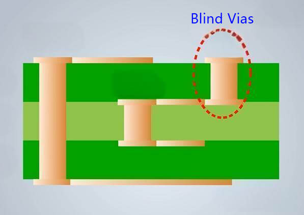
Blind vias are holes that enter the circuit board from one side without passing through the entire board. They are used to connect circuits between surface layers and internal layers. Blind vias support component soldering using surface mount technology (SMT) but cannot connect to the other side of the circuit board like through-hole vias.
FAQs
But before that, let us look at the rules of blind vias:
- Blind vias start from either the upper or lower layers of the board.
- It would help if you placed them on the layers evenly.
- Blind vias should not percolate the entire PCB.
- They should not start or end in the middle of the board substrate.
*Source:https://www.ourpcb.com
The number of manufacturing steps involved in this method of manufacturing blind vias makes it very expensive.
*Source:https://camptechii.com
A blind via connects an outer layer of the board to inner layers and doesn't go through the entire board. A buried via connects inner layers without reaching the outer layers. And a through hole via goes all the way through, from top to bottom, connecting all layers.
*Source:https://www.hemeixinpcb.com
A blind via connects to the next PCB layers, while a skip via can connect through multiple layers.
*Source:https://www.reddit.com
Some of the limitations of blind vias include:
Some fabricators require a diameter that is 1.5 times the depth. With a blind via the drilling needs to stop at the intended layer. With a laser drill, while the drill needs to go through copper on layer 1 in should not drill the copper connecting pad that is in layer 2.
*Source:https://www.technotronix.us
Zero Defect
Quick-turn service
PCBA Manufacture
Learn how Keep Best can turn your designs into products.

