


Potentiometers are very handy but sometimes a bit tricky to be wired in different ways. Ever had some problems understanding how these variable resistors should be connected in your audio equipment or other projects? You’re definitely not alone. Potentiometer wiring tends to puzzle many people.
Fear not, though; this article is here to help you out. We’re going to break it down in simple steps with clear diagrams and examples. By the time you’re through, you’ll know how to wire potentiometers correctly, no matter what configuration you need.
So, let us begin.
What is a Potentiometer
A potentiometer, often called a “pot,” is a type of variable resistor. The explanation is basically how this device controls or regulates voltage or current in a circuit; this control works by changing its own resistance value through manual tweaking. This very basic yet powerful device has applications across the vast spectrum of electronic devices, from audio gear to microcontrollers.
There are three terminals on potentiometers: two outer and one middle, which is called the wiper. This wiper travels along a resistive track so that when you turn the knob or slide the control, the resistance changes between it and the outer terminals.
Types of Potentiometers
There are several types of potentiometers suitable for different applications. Knowing these types might help you choose the appropriate potentiometer for your project.
1.Linear Potentiometers
In a linear pot, the movement of the wiper is proportional to changes in resistance. This means that while you are sliding the wiper along a resistive track, the resistance increases or decreases in a straight line.
Applications of linear potentiometers include: wherever precise, linear control is necessary—for example, sliders on audio mixing consoles.
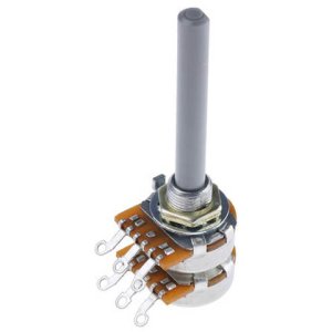
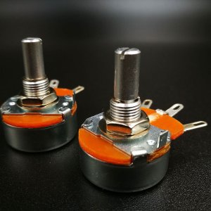
2.Rotary Potentiometers
Rotary potentiometers are the most common type. In these, changes in resistance take place with rotation of the knob. The wiper rides on a round resistive track, thus varying the resistance between wiper and outer terminals.
These have extensive applications in audio devices for volume, tone, and other control settings.
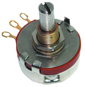
3.Single Turn Potentiometers
Single turn potentiometers achieve their entire range of resistance in just one full rotation of the knob. We find them quite easy to use and make fast adjustments.
These will do where a rapid coarse adjustment is necessary, such as in basic volume control or simple tuning circuits.
4.Multi-Turn Potentiometers
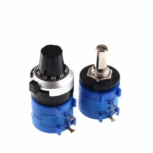
Multiturn potentiometers allow multiple turns—normally 10 or more—to be made for fine adjustment. As the wiper moves along this resistive track, changes are more gradual.
Those would be very appropriate for applications that require fine control within a small range, such as calibration equipment or trimming circuits.
5.Special Types of Potentiometers
Digital Potentiometers:
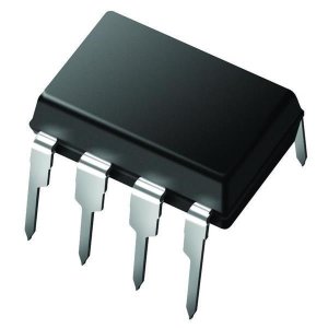
Digital potentiometers, or digipots, are controlled electronically rather than manually.
They are used in digital audio equipment and automated systems where a high degree of programmable control is required for applications.
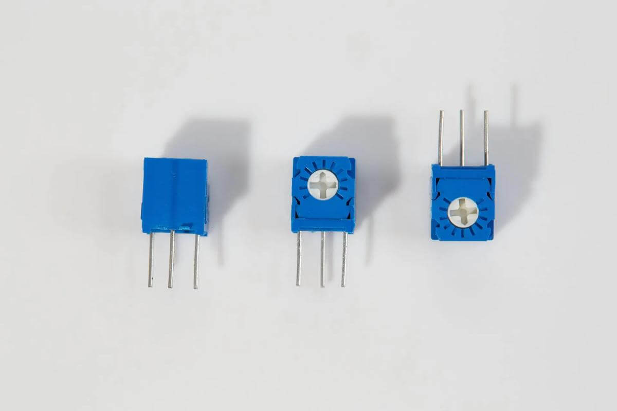
Trim Potentiometers
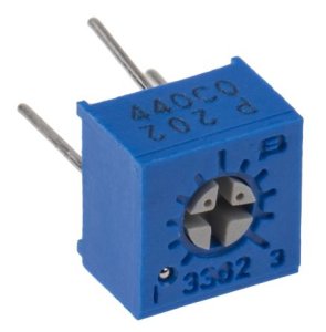
Trim potentiometers, also known as trimmers, are small potentiometers used as a means of fine adjustment in circuits. They are set once during calibration and rarely, if ever, ouched again.
These are used in circuits that require occasional adjustments, particularly in sensor calibration or biasing circuits.
Knowing these various types of potentiometers means that you can choose one for your intended use, ensuring maximum performance under any operating condition for your electronic projects.
Now you know the basics of potentiometers, it’s time to learn how to wire potentiometers in different configurations in detail.
Basic Potentiometer Wiring
Wiring a potentiometer correctly is crucial for its proper function in your circuit. Here, we’ll cover the fundamental aspects of potentiometer wiring, focusing on terminal identification and the most common wiring configuration: the voltage divider.
Terminal Identification
A potentiometer has three terminals:
- Wiper (Middle Pin): The movable contact that slides along the resistive track. This is typically the middle pin.
- Two Outer Terminals: The fixed ends of the resistive track. These are usually the outer pins.
Voltage Divider Configuration
The voltage divider is the most common way to wire a potentiometer. This setup allows you to vary the voltage output by adjusting the potentiometer.
Steps to Wire a Potentiometer as a Voltage Divider:
- Connect one outer terminal to the voltage source (e.g., Vcc).
- Connect the other outer terminal to the ground.
- Connect the wiper (middle terminal) to the input of the component you want to control (e.g., an LED or the input pin of an amplifier).
As you turn the potentiometer, the resistance between the wiper and each of the outer terminals changes. This, in turn, varies the voltage at the wiper, effectively controlling the voltage supplied to your component.
Diagram:
Here’s a simple diagram to illustrate basic potentiometer wiring as a voltage divider:
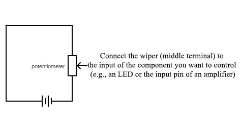
In this setup:
- The voltage at the wiper varies between 0V (ground) and Vcc as you turn the potentiometer.
- This configuration is ideal for adjusting the brightness of an LED, setting the input level of an amplifier, or any other application where you need to vary the voltage.
Advanced Wiring Examples
Once you understand the basics of potentiometer wiring, you can explore more advanced configurations for specific applications.
Here are a few practical examples demonstrating how to use potentiometers for LED brightness control, motor speed control, and microcontroller integration.
1.LED Brightness Control
Using a potentiometer to control the brightness of an LED is a common application. This example extends the basic voltage divider setup to adjust the LED’s brightness.
Steps to Wire a Potentiometer for LED Brightness Control:
- Connect one outer terminal of the potentiometer to the positive terminal of the power supply (e.g., 5V or 12V).
- Connect the other outer terminal to the ground.
- Connect the wiper (middle terminal) to the positive leg (anode) of the LED.
- Connect the negative leg (cathode) of the LED to a current-limiting resistor.
- Connect the other end of the resistor to the ground.
Diagram:
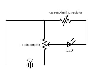
Explanation:
- As you turn the potentiometer, the voltage across the LED changes, altering its brightness.
- This setup allows for smooth adjustment of the LED’s brightness.
2.Motor Speed Control (Simple)
You can also use a potentiometer to control the speed of a small DC motor. This example uses the potentiometer to vary the input voltage to a motor driver circuit.
Steps to Wire a Potentiometer for Motor Speed Control:
- Connect one outer terminal of the potentiometer to the positive terminal of the power supply.
- Connect the other outer terminal to the ground.
- Connect the wiper (middle terminal) to the input of the motor driver circuit.
- Connect the motor driver output to the motor.
Diagram:
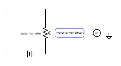
Explanation:
- Turning the potentiometer changes the voltage sent to the motor driver.
- The motor driver then adjusts the speed of the motor based on this input voltage.
Safety Precautions:
- Ensure that the motor and power supply are compatible with the potentiometer’s specifications to avoid damage.
- Use appropriate current-limiting components to protect your circuit.
3.Microcontroller Integration
For more advanced applications, you can connect a potentiometer to a microcontroller, like an Arduino, to provide analog input and control various outputs.
Steps to Wire a Potentiometer to an Arduino:
- Connect one outer terminal of the potentiometer to the 5V pin of the Arduino.
- Connect the other outer terminal to the GND pin.
- Connect the wiper (middle terminal) to one of the analog input pins (e.g., A0).
Diagram:
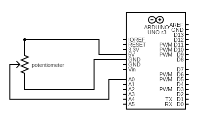
Explanation:
- The Arduino reads the voltage from the wiper as an analog input.
- You can use this input to control various outputs, such as LED brightness, motor speed, or other actuators, through programming.
Troubleshooting Potentiometer Wiring
Even with careful setup, you might encounter issues when wiring potentiometers.
Here are some common problems and their solutions to help you troubleshoot potentiometer wiring effectively.
- No Response from Potentiometer
If your potentiometer doesn’t seem to adjust anything in the circuit, start by checking all connections. Make sure they are secure and correctly wired. Ensure the wiper is connected to the right input. Use a multimeter to check for continuity between the terminals.
If there’s no continuity, the potentiometer might be faulty. Also, check that the power supply is correctly connected and providing the necessary voltage.
- Inconsistent or Erratic Behavior
If the output is unstable or jumps unpredictably when you adjust the potentiometer, the contacts might be dirty. Dust or oxidation can cause poor contact.
Clean the potentiometer’s terminals and wiper with contact cleaner. Look for physical damage or wear on the potentiometer and replace it if necessary. Ensure the power supply is stable and not fluctuating, as this can affect the potentiometer’s performance.
- Limited Range of Adjustment
Sometimes, the potentiometer may only adjust the output over a small portion of its range. Check that the potentiometer is wired correctly as a voltage divider. Incorrect wiring can limit the adjustment range.
Also, ensure the potentiometer’s resistance value is suitable for your application. Using a potentiometer with too high or too low a resistance can restrict the adjustment range, so choose one that fits your circuit’s needs.
- No Change in LED Brightness
If the LED brightness doesn’t change when you adjust the potentiometer, check the connections. Make sure the potentiometer’s wiper is correctly connected to the LED circuit. Verify that the current-limiting resistor is in place and has the right value.
Also, check that the LED is oriented correctly, with the anode connected to the potentiometer wiper and the cathode to the ground.
- Motor Speed Not Changing
If the motor speed doesn’t change even when you adjust the potentiometer, the motor driver might be the problem. Ensure the motor driver is working correctly and receiving input from the potentiometer.
Check that the power supply is adequate for both the motor and the potentiometer. Double-check that the potentiometer is wired correctly to the motor driver’s input to control the motor speed as intended.
Conclusion
Wiring potentiometers can be tricky, but it’s easier once you understand the basics. We have gone over how to identify the terminals, use the voltage divider setup, and apply potentiometers in different ways, like controlling LED brightness, motor speed, and connecting to microcontrollers.