


Are you confused by all the symbols on your multimeter? You are not alone. Working out what each symbol means can be confusing, mainly if you’re starting out. Knowing these symbols is the clue to getting accurate readings and staying safe.
But worry not as this article will explain each symbol, what it does for you, and how to use it. By the end, you’ll be using your multimeter with much more confidence in any situation.
Now, let’s get started.
Understanding Multimeters
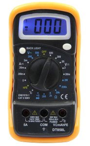
Before getting straight to understand the multimeter symbols, it’s essential to first understand multimeters.
A multimeter is used to measure several electrical properties of voltage, current, and resistance. It contains the functions of several meters in one unit, so it is very essential for any person servicing electronic or electrical units.
Basically, multimeters fall into two types: analog and digital. Analog multimeters have a needle and scale that display the readings, while digital multimeters have measurements on a digital display screen. In principle, they perform the same functions but in different ways.
Why do Symbols Matter
The multimeter’s symbols are like the stars that guide through the device’s varied functions. Each symbol stands for some sort of measurement kind or setting, in a way letting one choose the correct mode for his testing needs. Knowing these symbols assures you of accurate results and safety in using the multimeter.
Common Multimeter Symbols
You will see lots of symbols on your multimeter and understanding them might be confusing for you.
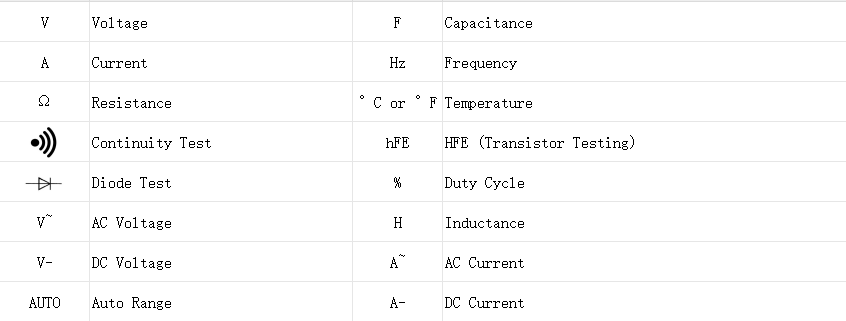
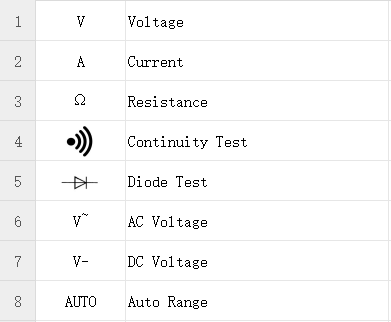
So first let’s discuss some common multimeter symbols:
1.Voltage (V)
- Symbol:V
- What It Means:Measures electrical potential difference between two points. This can be either direct current (DC) or alternating current (AC).
2.Current (A)
- Symbol:A
- What It Means:Measures the flow of electric charge through a circuit. You might see this symbol with a ‘m’ (for milliamps) indicating a smaller unit.
3.Resistance (Ω)
- Symbol:Ω
- What It Means:Measures how much a component resists the flow of current. It’s important for checking connections and components.
4.Continuity Test
- Symbol:A sound wave or a diode symbol with a line
- What It Means:Checks if there’s a complete path for current to flow. If the circuit is complete, the multimeter usually beeps.
5.Diode Test
- Symbol:A diode triangle with a line
- What It Means:Tests the functionality of diodes by measuring the voltage drop across them.
6.AC Voltage (V~)
- Symbol:V~ or a wavy line
- What It Means:Measures alternating current voltage, which varies in direction and magnitude.
7.DC Voltage (V-)
- Symbol:V- or a straight line with a dashed line below it
- What It Means:Measures direct current voltage, which flows in one direction only.
8.Auto Range
- Symbol:An “A” with a range or “AUTO”
- What It Means:Automatically selects the best range for the measurement being taken, simplifying the process.
Advanced Multimeter Symbols and Their Meanings
Once you are comfortable with the basic multimeter symbols, it’s time to discuss some of the advanced symbols that can help you perform specialized measurements.
Here they are:
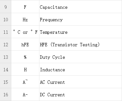
9.Capacitance (F)
- Symbol:F (Farads)
- What It Means:Measures the capacitance of capacitors. The symbol might be accompanied by “CAP” or an arrow pointing to a capacitor symbol.
10.Frequency (Hz)
- Symbol:Hz
- What It Means:Measures the frequency of an AC signal. This is useful for checking signal cycles per second.
11.Temperature (°C or °F)
- Symbol:°C or °F
- What It Means:Measures temperature, typically using a thermocouple or temperature probe connected to the multimeter.
12.HFE (Transistor Testing)
- Symbol:HFE with a transistor icon
- What It Means:Tests the gain of a transistor and identifies its type (NPN or PNP).
13.Duty Cycle (%)
- Symbol:A percentage sign %
- What It Means:Measures the duty cycle of a signal, which is the ratio of the signal’s high period to the total period.
14.Inductance (H)
- Symbol:H (Henrys)
- What It Means:Measures the inductance of inductors. This symbol might also appear as “L” in some meters.
15.AC Current (A~)
- Symbol:A~ or a wavy line with an “A”
- What It Means:Measures the flow of AC current through a circuit.
16.DC Current (A-)
- Symbol:A- or a straight line with an “A”
- What It Means:Measures the flow of DC current.
By understanding these symbols, you can take full advantage of your multimeter’s capabilities.
What Are The Units of a Multimeter
Multimeters measure various electrical properties, and understanding the units they use is crucial for accurate readings.
Here are the key units you will encounter:
1.Volts (V)
- Used For:Measuring voltage.
Voltage is the potential difference between two points in a circuit. It can be expressed in both direct current (DC) and alternating current (AC). For DC, the symbol is V- or VDC, and for AC, it’s V~ or VAC.
2.Amperes (A)
- Used For:Measuring current.
Current is the flow of electric charge through a circuit. It can be measured in milliamps (mA) or microamps (µA) for lower ranges. For example, 200mA indicates a maximum measurement of 200 milliamps.
3.Ohms (Ω)
- Used For:Measuring resistance.
Resistance is the opposition to the flow of current. It’s measured in ohms, and the symbol is Ω. High resistance means less current flow, while low resistance means more current.
4.Farads (F)
- Used For:Measuring capacitance.
Capacitance is the ability of a component to store an electrical charge. Multimeters that measure capacitance will use this unit, though it might appear as microfarads (µF) or nanofarads (nF) for more precise measurements.
5.Hertz (Hz)
- Used For:Measuring frequency.
Frequency measures how many cycles of an AC signal occur per second. The unit Hertz (Hz) indicates the frequency of the signal.
6.Degrees Celsius (°C) or Fahrenheit (°F)
- Used For:Measuring temperature.
Temperature measurements are indicated in degrees Celsius or Fahrenheit, depending on the probe used with the multimeter.
What Does 200m Mean on a Multimeter?
The “200m” setting on a multimeter typically refers to a range that measures electrical values in millivolts (mV). This setting allows the multimeter to measure small voltage levels accurately, with the “200m” indicating a maximum range of 200 millivolts.
When you see “200m” on your multimeter:
- Voltage Measurements:It means you’re set to measure voltages up to 200 millivolts.
- Precision:This setting is useful for checking low voltage signals or components where precision is crucial.
Switching to this range allows the multimeter to display measurements with greater detail, which is essential for detecting minor voltage variations.
What Is the Symbol for DC Volts?
The symbol for DC volts on a multimeter is typically a straight line with a dashed line beneath it, represented as V- or VDC.
- Symbol:V- or VDC
- What It Means:This symbol indicates that the multimeter is set to measure direct current (DC) voltage, which flows in one direction only.
In some multimeters, you might also see a straight line with three dots below it (— or —|), which represents DC voltage. Understanding this symbol helps you select the correct mode for measuring steady, unidirectional voltage in your circuits.
Multimeter Safety Measures
Using a multimeter safely is crucial to avoid accidents and ensure accurate measurements.
Here are some essential safety tips to follow:
- Check the Multimeter
Inspect the multimeter and its leads for any signs of damage, such as frayed wires or cracks. Do not use the multimeter if you notice any defects.
- Use the Correct Settings
Always set the multimeter to the correct measurement function (voltage, current, resistance) and range. Incorrect settings can lead to inaccurate readings or damage to the multimeter.
- Be Cautious with High Voltage
When measuring high voltages, ensure you’re using the correct range and that your multimeter is rated for the voltage you’re testing. Always keep your fingers behind the insulation on the probes to avoid contact with live wires.
- Avoid Measuring Current in Parallel
When measuring current, connect the multimeter in series with the circuit. Measuring current in parallel can cause a short circuit, leading to potential damage or injury.
- Use Proper Leads
Use leads that are in good condition and appropriate for the measurement being taken. Ensure they are securely connected to both the multimeter and the circuit.
PCB Faults You Can Detect Using a Multimeter
A multimeter is a powerful tool for diagnosing issues on a printed circuit board.
Here are some common PCB faults you can detect using a multimeter:
1.) Short Circuits
A short circuit occurs when electricity takes an unintended path, which can damage components or cause overheating. To find a short circuit, use the continuity test on your multimeter.
Place the probes at different points on the PCB. If the multimeter beeps or shows continuity, it means there’s a short circuit somewhere between those points. Fixing short circuits is important to prevent further damage and ensure your circuit works properly.
2.) Open Circuits
An open circuit happens when there’s a break in the connection, stopping current flow. This can be due to broken traces or loose connections. To find an open circuit, use the continuity test on your multimeter.
Place the probes at different points. If there’s no beep or continuity, it means there’s a break in the circuit. Finding and fixing open circuits helps your PCB function correctly.
3.) Component Failures
Components like resistors, capacitors, and diodes can fail and cause problems.
Test them with your multimeter:
- Resistors:Measure the resistance to see if it matches the expected value.
- Capacitors:Check the capacitance (if your multimeter has this feature) to see if it’s within range.
- Diodes:Use the diode test to check if it’s working in the right direction. If a component isn’t working as it should, it may need replacing.
If you are interested in using a multimeter to detect PCB, you can read this article:
How To Test A PCB With A Multimeter
How to Do a Diode Check on a Multimeter
Here are the steps that will help you:
- Make sure the circuit is powered off before testing to avoid damage and get accurate results.
- Switch your multimeter to the diode test mode, usually marked with a diode symbol (→|).
- Attach the red probe to the positive side and the black probe to the negative side of the diode.
- The multimeter should show a small voltage drop (usually between 0.5V and 0.7V). This means the diode is working and allowing current to flow in one direction.
- Swap the probes (red to negative and black to positive). The multimeter should show no reading or a high resistance, indicating the diode is blocking current in the reverse direction. If it shows a reading, the diode may be faulty.
How to Check the Polarity of a Capacitor Using a Multimeter
Here’s how you can check the polarity of a capacitor using a multimeter:
- Ensure the circuit is turned off and the capacitor is fully discharged before testing.
- If your multimeter can measure capacitance, set it to the capacitance mode. If not, check the polarity manually.
- Look for the positive (+) and negative (−) leads on the capacitor. The positive lead often has a stripe or “+” sign.
- Attach the red probe to the positive lead and the black probe to the negative lead of the capacitor.
- Now you will have to check for readings:
- If Measuring Capacitance:The multimeter should display a value close to the capacitor’s rating. If it shows nothing or a very low number, the capacitor might be bad.
- If Checking Polarity Manually:Make sure the positive lead of the capacitor is connected to the positive side of the circuit and the negative lead to the negative side. Proper polarity is important for the capacitor to work correctly.
By following these steps, you can easily check diodes and capacitors to ensure they are functioning properly.
Conclusion
Understanding multimeter symbols helps you take accurate measurements and fix problems with electronics. Whether you’re checking voltage, current, or more advanced features like capacitance, knowing these symbols makes using your multimeter easier.
Remember to always follow safety guidelines to avoid accidents. With this guide, you will be better equipped to handle your electrical projects and troubleshoot issues effectively.