Are you wondering what are PCB Diodes or how do they function? Learning about these small yet important components can be quite daunting. Be it difficulty choosing the best diode for your design or problems with the existing ones, you’re not alone.
We’ll take a closer look at everything you need to understand regarding PCB diodes, from their primary functions down to choosing the perfect type for your needs. We will also discuss test equipment and common problems associated with them and how to troubleshoot.
So, let’s get started.
What is a PCB Diode
A diode is a fundamental electronic component with two terminals, designed to allow current to flow in one direction only. This current conduction characteristic, though unidirectional, makes the component important in controlling the direction of the current conduction in many different electronic circuits.
Diodes help to prevent damage to the other circuit components, allowing conduction in the forward direction of current and resisting conduction of the reverse current.
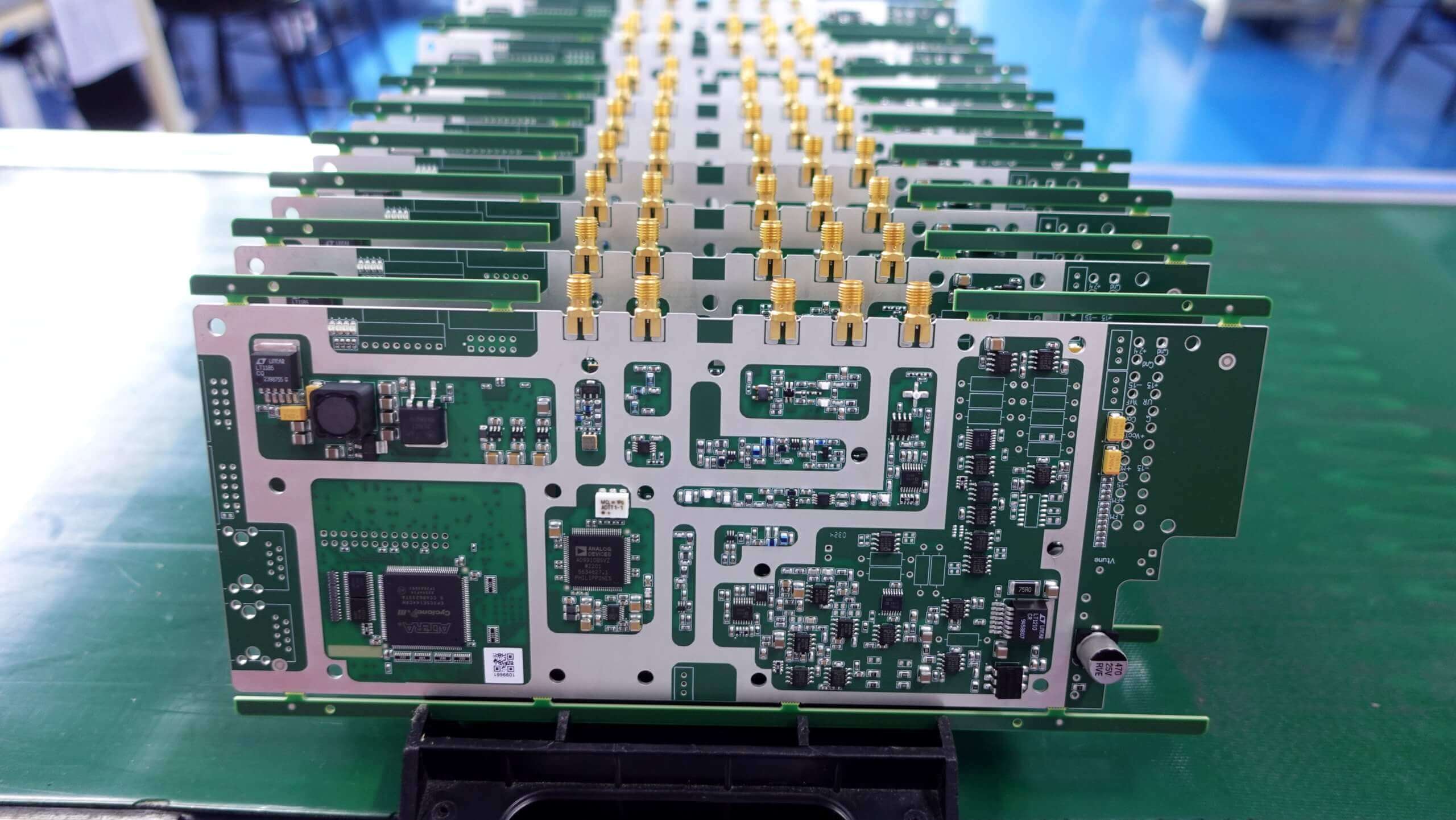
PCB diodes are specifically made for mounting on printed circuit boards so that the diodes can come in through-hole packages suitable for SMT applications as well.
The integration of diode directly into PCBs in this manner makes direct and small, practical circuits electronic. Therefore making them versatile for use in a wide range of equipment, inclusive of power supplies and signal processing.
Types of PCB Diodes
There are different types of PCB Diodes available. The most important ones are:
- Rectifier Diodes
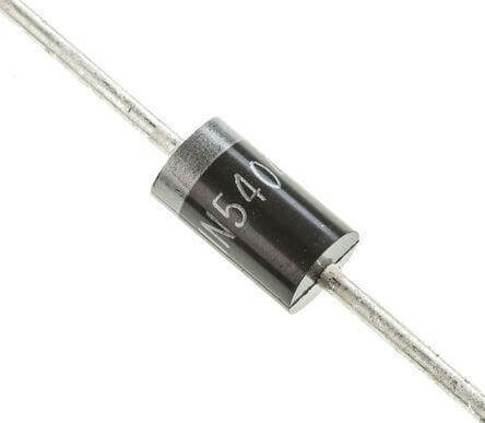
Rectifier diodes are built to only allow current in one direction; hence, they are essential in converting alternating current, AC, to direct current, DC.
The diodes often find applicability when there is a need to supply power, converting AC from the power outlet into DC.
Rectifier diodes block the backflow of current, therefore protecting a circuit from any damage that could have been realized due to reverse voltage.
- Zener Diodes
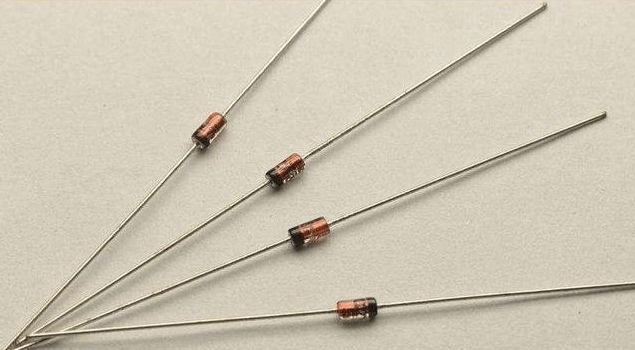
Zener diodes are unique in their ability to regulate voltage. They allow current to flow in the reverse direction when a specific voltage threshold, known as the Zener breakdown voltage, is reached.
They are, hence, effectively utilized in voltage control applications found in circuits. A Zener diode is further seen in applications where a consistent voltage delivered is necessarily consistent, such as power supply and voltage reference circuits.
- Schottky Diodes
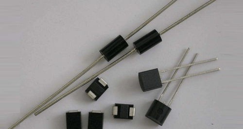
Schottky diodes feature fast switching rates and a lower forward voltage drop than regular rectifier diodes. It means that they can switch on and off faster and better to fit in high-speed and high-efficiency uses.
Generally, Schottky diodes are helpful in rectification of power, RF applications, and cases whereby power loss needs minimization.
- Light-Emitting Diodes (LEDs)
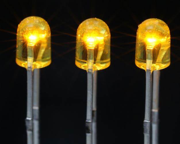
LEDs are effectively light-producing diodes following the passage of current. Unlike ordinary diodes, LEDs find almost all limit usage for their ability to light up.
So, light-emitting diodes have numerous applications in indicators, digital displays, everyday lighting purposes, and advanced signaling. LEDs quickly became extremely popular as an energy-saving device with extra-long life, as well as having adjustable color and light intensity.
Understanding Diode Operation
A diode consists of two semiconductor materials, typically silicon, joined together to form a p-n junction. When these materials are fused, they form a depletion region at the junction where charge carriers combine and cancel each other out, creating a barrier.
Operational Principles
1.Forward Bias
The diode is forward biased when the p-side connects to the positive terminal of a power source and the n-side connects to the negative terminal.
The external voltage reduces the width of the depletion region; hence as a result, the diode allows current to flow through itself.
The forward voltage drop is typically 0.7V for silicon devices and is the energy that must be spent to exceed the barrier.
2.Reverse Bias
When the positive terminal is connected to the n-side and the negative terminal to the p-side, the diode is reverse biased.
The external voltage causes the depletion region to increase in width, thus blocking the conduction band of current.
As a result of minority carriers, there might be a small leakage current flowing, although this contribution usually remains relatively small.
3.Breakdown
If the reverse bias voltage exceeds a certain threshold, known as the breakdown voltage, the diode will conduct in reverse.
This is potentially destructive unless the diode is designed for such conditions as the Zener diode.
So that’s how PCB Diodes work. Now let’s learn how you can choose the right diode for your PCB design.
Selecting the Right Diode for Your PCB Design
Selecting the suitable diode during printed circuit board design is a very imperative step to ensure the reliability and performance of the circuit.
The following are the key factors that must be taken into consideration while choosing a diode:
- Function
First, determine what you would like your diode to do in your circuit. Diodes can do various things: rectification, regulating voltage, protection, and switching.
As a simple illustration of this, power supplies incorporate rectifier diodes for converting AC to DC. Zener diodes are used to stabilize the voltage. Protection diodes such as TVS diodes will ensure the safety of your circuit under abnormal voltage conditions.
Schottky diodes are excellent for high-speed switching, and LEDs are used for lamps and displays. Knowing its function helps you in selecting the right kind of diode.
- Voltage Rating
Use a diode with a voltage rating higher than the highest it will encounter in your circuit. This way, the diode does not break down during a voltage spike.
Since the peak value of your AC voltage is 50V, use a diode with a reverse voltage rating of at least 75V to ensure the diode will not experience this voltage corona and break.
- Current Rating
Choose a diode capable of allowing the current flow in the circuit without being overheated. The current rating is greater than the maximum expected current.
For a diode, with a peak current in your circuit rated at 2A, choose a diode that is rated at 3A or higher. This way, your diode has a specified rating high enough so that it doesn’t overheat, causing the diode.
- Power Dissipation
Make sure that the diode has enough power dissipation for its working environment. To find the power dissipation, multiply the forward voltage drop by the current.
If a diode has a forward voltage drop of 0.7V and the current is 2A, it dissipates 1.4W. One would need to ensure that the diode is capable of the excess heat, whether from its self-operating heat sinks or additional cooling means.
- Package and Mounting
Consider how you envision your diode being mounted on your PCB. Diodes are packaged in one of two ways: through-hole (THD) or surface-mount (SMD). Of these two, through-hole diodes are more accessible to replace. But they typically consume more space on the board.
The most important application of surface-mount diodes is to facilitate a compact and automated PCBA. Select package type either for your PCB layout or for your manufacturing process.
- Cost
It is always necessary to balance how desirable the features and performance of a diode are against the consideration of how much they cost. High-performance diodes will be expensive.
Look at what your circuit requires of the diode, then select a diode that meets those requirements without overspending.
For example, if your design doesn’t require high-speed switching, then you can get a rectifier, but it is cheaper than a Schottky diode. This way, you choose the cheapest diode that will give you good value based on the diode application.
Applications of PCB Diodes
The applications of the PCB diodes are just too many to list—all electronic circuits are actually swarmed with them.
Some of the more common:
1.Power Supplies
Diodes are critical components that are used to convert Alternating Current (AC) to Direct Current (DC) power.
Rectifier diodes are thus designed with a well-defined forward voltage drop for including power from an AC source rectification into a sufficiently constant DC output for end electronic devices and equipment.
2.Voltage Regulators
The Zener diode is used in voltage regulation circuits so that a constant voltage can be maintained at the output over some permissible range of output voltage. In this way, it allows conduction in the reverse way when the applied voltage lies above a determined value.
Thus, they ensure voltage maintenance at the same level for different loads.
3.Protection Circuits
TVS diodes are actually used in protection circuits to safeguard sensitive electronic components against voltage spikes and surges.
The fast ability of these diodes to absorb excess voltage diverts potentially damaging currents away from delicate circuitry, helping to ensure reliable operation even under fluctuating electrical environments.
4.Logic Circuits
Diodes are an essential base for all logic circuitry in implementing a set of different logic functions and signal-level-shifting functions.
They are used to permit current to control the reconfigured operation of digitized signal switching and processing—elements of utmost importance for all types of computing and communication devices.
5.LED Lighting
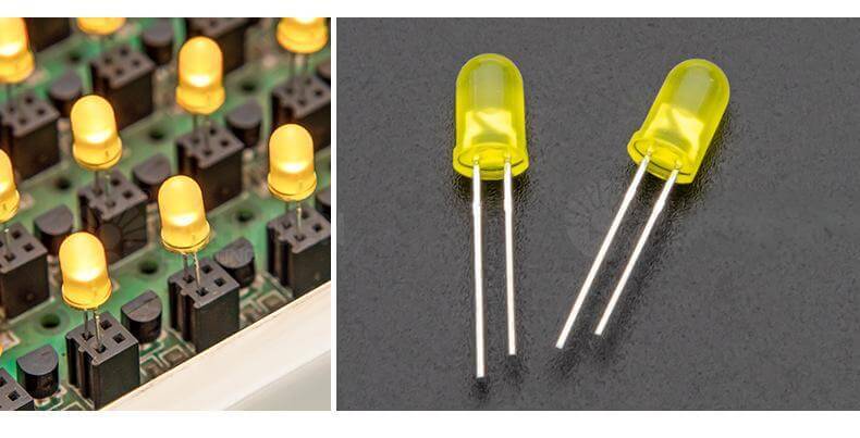
Light-emitting diodes (LEDs) are driven by diode circuits in lighting and display applications. Diodes control the current flowing through LEDs, ensuring optimal brightness and longevity while providing energy-efficient illumination in diverse settings such as residential lighting, automotive lighting, and electronic displays.
Troubleshooting Diode-Related Issues
Here are some practical tips that will help you troubleshoot and fix diode related issues:
Open Circuit
An open circuit occurs when the diode fails to conduct electricity in either direction, indicating a possible fault:
- Diagnosis: Use a multimeter set to diode mode to test if there’s any voltage drop across the diode in both forward and reverse directions.
- Solution: If the multimeter shows no voltage drop in either direction, it suggests the diode is faulty. Replace it with a new diode that matches the same type and specifications to restore proper functionality.
Short Circuit
A short circuit happens when the diode conducts electricity in both forward and reverse directions, which is not normal:
- Diagnosis: Use a multimeter to check for continuity or low resistance in both directions.
- Solution: If the diode conducts in both directions, it has likely failed. Replace it with a new diode that meets the circuit’s requirements to prevent further issues.
Incorrect Diode Selection
Choosing a diode with incorrect voltage or current ratings can lead to performance problems:
- Diagnosis: Review the circuit specifications and compare them with the diode’s datasheet to ensure it matches the required voltage and current ratings.
- Solution: If the diode does not meet the circuit’s specifications, replace it with one that has the appropriate ratings. This ensures the circuit operates correctly and avoids potential damage or malfunction due to mismatched components.
Conclusion
In conclusion, understanding PCB diodes is crucial for designing and fixing electronic circuits effectively. These small yet important components, like rectifier, Zener, Schottky diodes, and LEDs, serve various roles from converting power to protecting circuits.
With this knowledge, you can confidently handle PCB diodes in your projects.

