


Flex-rigid PCBs are one of the most efficient types of Printed Circuit Boards, combining the benefits of both flexible and rigid PCBs. Consisting of rigid sections connected by flexible layers, they possess multiple advantages due to their increased design flexibility and space-effective use.
This detailed guide to designing one will focus on the benefits and applications of flex-rigid PCBs. It will explain the design process for various cases with detailed instructions.
What Are Flex-Rigid PCBs
Flex-rigid boards are circuit boards comprising single or multiple rigid sections and sections that connect these rigid parts. The rigid structures work as a backbone to which the parts are fastened and from which they hang loosely away.
The flex functions the same way and makes the board foldable. For applications requiring multiple configurations or with limited space, these board types’ combination offers various design opportunities brought about by their flexibility.
The most common methods of forming connections between the rigid and flex parts include surface mount technology and plated through-hole connectors. This integration form produces electrically and mechanically impeccable attachments and is suitable for small, intricate electronic devices.
Advantages Of Flex-Rigid PCBs over Rigid PCBs
Flex-rigid PCBs have many advantages compared to standard rigid PCBs, making them a preferable choice in many applications:
1. Space savings
The flexible parts of flex-rigid PCBs can be folded and bent, allowing them to be used in tight and unconventional spaces that rigid PCBs used to be unable to. This is particularly useful in small devices where space is a critical concern. Flex-rigid PCBs can be tailored to odd enclosures and distinct form factors and offer a solution that rigid boards cannot.
2. Improved functionality
The flex-rigid PCB eliminates the necessity for multiple connectors and interconnects, which are inevitable in designs involving multiple simple rigid PCBs. This, in turn, reduces the number of potential points of failure and thus improves reliability and performance. Removing connectors simplifies the assembly, while the signal integrity is higher due to the lower number of connection points.
3. Design Flexibility
The fact that mechanics and bends can be implemented in the part design allows you to work with three-dimensional configurations, which is impossible with rigid boards exclusively. This, in turn, provides an excellent opportunity to create innovative devices such as wearables, IoT devices, and other mobile gadgets. As a coherent result, moving elements and certain action mechanisms are allowed, which paves the way for advanced, multifunctional devices.
Applications Of Flex-Rigid PCBs
Flex-rigid PCBs fit into intricate and limited places and are distinctive in their flexibility and rigidity, making them useful in various applications. The following are some important applications:
1. Wearable electronics
These are suitable for smartwatches, fitness trackers, and smart clothing. Flex-rigid Printed Circuit Boards (PCBs) can bend, assume different shapes, and ensure optimal functional ability. They make lightweight, folding designs that improve user comfort and convenience.
2. Medical devices
Flex-rigid PCBs are vital in diagnostic equipment, such as MRI and CT scanners, where they must be reliable and compact. Because of their flexibility, they are also incorporated in implantable devices, like pacemakers and cochlear implants, which enables them to remain functional within the human body.
3. Automotive Electronics
Long-term reliable operation and compact and efficient designs are only possible with flex-rigid PCBs for modern cars’ infotainment systems, sensors, control units, and ABS sensors. They endure even the harshest conditions of vibrations and temperature drops and fluctuations.
Designing Flex-Rigid PCBs: Step-by-Step Guide
Designing flex-rigid PCBs may seem daunting; however, with a structured approach, it is manageable and efficient. This guide outlines the entire process of designing flex-rigid PCBs, starting with identifying design requirements and culminating in assessing manufacturability.
1. Defining Design Requirements
Before designing, the design requirements must be articulated. These include the flexibility needed, the maximum bend radius the element can take without damage, and the environmental demands. Others are whether the flex’s elements will be creased rub, dynamic, or static. These requirements help create a design that facilitates mechanical and electrical performance.
2. Material Selection
Material selection for both the rigid and flexible sections is equally essential. Polyimide is often ideal for flexible sections due to its flexibility and thermal stability, while FR4 provides the appropriate rigidity and structure for rigid sections. However, it bears repeating that properties such as mechanical strength, electrical function, and material compatibility between sections should be considered. Select materials with a high thermodynamic cycling tolerance in dynamic bending implementations.
3. Stackup Design
The initial phase in PCB creation involves configuring the board layers through stackup design. The layer configuration is optimised in rigid and flexible sections to enhance structural robustness and functionality. The signal is properly implemented when the stack-up design is in place. Flex layers of placement are kept as minimal as possible to reduce stress and attain optimal operations. Ground planes use cross-hatch patterns to establish a flexible but electrically conductive ground.
4. Schematic Capture
The next step involves creating a schematic. This diagram shows the electrical connections in the circuit and maps how the components will be integrated into the PCB. This interactive map shows the precise placement and relation of the components, ensuring that all electrical needs are fulfilled. A seamless transition to the layout stage is solely possible if a perfectly captured schematic is available.
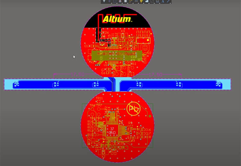
5. PCB Layout
Afterwards, it is crucial to lay out the flex-rigid PCB with the help of appropriate design software. It is important to outline the differences in rigid and flexible areas, put components in a way that allows them to be manufactured and guarantees proper signal transmission, and implement relevant routing strategies. Some of the considerations include component position, routing, and signal integrity. Curved traces may be placed in a flexible area to avoid creating tension concentrations causing potential fractures.
6. Routing
Routing traces on a flex-rigid PCB faces limitations such as bend radius, stress, and maintaining signal integrity. However, one can improve flexibility and durability by implementing curved traces and cross-hatch patterns. Technicians should also ensure that traces are routed perpendicular to the bend lines and avoid putting the vias and pads at the angle of bending to minimise mechanical stress.
7. Design for Manufacturing (DFM)
It is important to remember DFM principles during the designing phase. Factors such as minimum bend radius, placement limitations, and assembly implications might lead to production problems. These are to ensure the design can be easily manufactured with high yields. This might entail the number of layers or the total complexity of the flex PCB stack.
Specific Challenges In Flex-Rigid PCB Design
Flex-rigid PCB design has special difficulties that need to be carefully considered. Here are the main things to concentrate on:
1. Flex Zone Design
It should include a bend radius and design considerations to manage stress. These zones should be able to bend several times without causing damage to the traces. In dynamic applications, use materials that allow the material to continuously flex and gently route the trace to reduce stress by using curved traces and avoiding right angles.
2. Material Compatibility
Materials’ rigidity and flexibility, including thermal expansion coefficients, should be compatible, as mismatched materials lead to delamination and structural defects. Polyimide is chosen for its flexibility and thermal stability, whereas FR4 is the more appropriate option for rigidity. Proper material selection ensures the durability and reliability of the rigid-flex circuit boards.
3. Manufacturing Considerations
For the highly complex and expensive fabrication process, for example, flex-rigid PCBs, arrange a collaborative project with the PCB manufacturers to discuss particular issues and ways to optimise the design to lower production costs.
For instance, this may refer to the minimum bend radius via placement and assembly considerations: such tricks as cross-hatching in the ground planes increase flexibility and decrease stress. Discuss the potential complications in the early stages to facilitate smoother production and enhance etch yields.
Specific Guidelines For Flex-Rigid PCB Design
Following these guidelines will help you avoid common errors and enhance the durability and performance of your PCB. Let’s explore these essential rules to ensure your design process runs smoothly.
- Avoid Plated Through Holes on Bending Areas: Mechanical stress on the plated holes should similarly be avoided as it weakens the viability of the pads and vias.
- Proper routing across bending areas:Traces on bending areas should be kept straight and perpendicular, with narrower traces and dummy traces on both sides enhancing mechanical sturdiness.
- Cross-Hatched Ground Planes:Instead of solid copper, use cross-hatched ground planes in flexible areas to provide flexibility without much stress.
- Heat dissipation: the design should be able to dissipate heat to power effective performance and eliminate any chance of damage.
Material stack up: Work with the fabricator to select the best material stack up, considering the UL flammability rating, bend radius, and RoHS certification.
Conclusion
Designing flex-rigid PCBs is a complicated process that combines flexibility, multifunctionality, and manufacturability. Once you know the peculiarities and problems of flex-rigid PCBs, you can develop more sophisticated and dependable electronic devices that will significantly strengthen the growing requirements of current technology.
By following the guide, you guarantee that your flex-rigid PCBs are perfectly engineered for operation and endurance, opening up new possibilities for the future of electronic devices.